
1-805-484-2992
Quotes - Engineering - Sales| PRODUCT | STYLE | DRAFT | COOLING MEDIUM |
| Vapor Condenser | Horizontal Fin Fan | Forced or Induced | Ambient Air |
Horizontal Fin Fan Condensers
Flat Bundle, Accessible Fins, Wide Materials Range
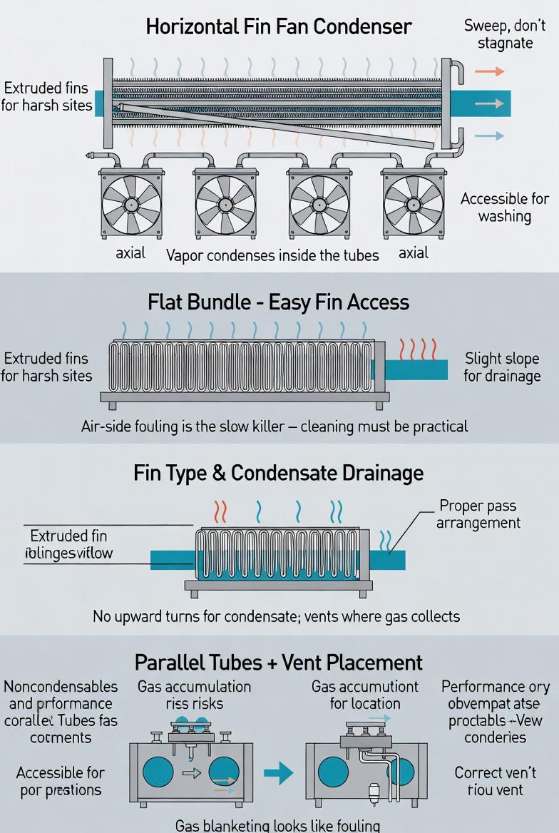
A horizontal fin fan condenser is a flat, rectangular bundle of finned tubes mounted in a plenum with axial fans moving ambient air through it. Vapor condenses inside the tubes and the latent heat leaves with the air. It is the most common air cooled arrangement in process plants, and its virtues are practical rather than exotic.
Access is the main one. A horizontal bundle sits at a workable height with the fin surface presented flat. Fins can be inspected, washed and cleaned without scaffolding gymnastics, which matters because air-side fouling is the slow killer of air cooled performance. Dust, pollen, insects, process fallout and cottonwood all lodge between fins, and a bundle that is awkward to clean does not get cleaned.
Fin type decides service life. Extruded fins, where an aluminum sleeve is extruded over the tube, give the best protection against atmospheric corrosion and the most stable long-term thermal performance because the bond cannot loosen. L-foot and wrapped fins are cheaper and perfectly adequate in benign atmospheres, but the mechanical bond can relax over years of thermal cycling, and a loosened fin transfers heat poorly. On coastal, chemical or heavily-industrial sites, extruded or embedded fins are usually worth the difference.
Tube-side condensing constraints. Because the vapor condenses inside the tubes, the bundle must be arranged so condensate can leave. Horizontal tubes with a slight slope toward the outlet header, careful pass arrangement and generous outlet nozzles all matter. Multi-pass arrangements need particular attention: a pass that turns upward asks condensate to climb, and it will not, so it accumulates and floods surface from that point back.
Where noncondensables collect. A horizontal bundle has many parallel tubes fed from a common header. Gas migrates toward whichever tubes have the lowest flow, blankets them and takes them out of service, while the rest of the bundle carries on. The result is a unit that quietly loses capacity in a way that looks like fouling. Vent connections positioned where gas actually accumulates, and pass arrangements that sweep rather than stagnate, are the answer.
For very large vapor volumes and steam duty see V-bank and A-frame arrangements; for the fan question see draft arrangements.
Horizontal Fin Fan Configuration
Bundle geometry, fin type and fan arrangement are all set by the duty, the site ambient conditions and the atmosphere the unit has to survive in.
Configuration
- Bundle: Horizontal finned
- Fin Types: Extruded, L-foot, embedded
- Fans: Axial, VFD optional
- Vapor Side: Inside tubes
Features
- Accessible fin surface
- Low profile installation
- Wide tube alloy range
- Multi-pass arrangements
- Fan speed control option
Typical Condensing Duty
- Process vapor condensing
- Solvent recovery duty
- Overhead condensing
- Refrigerant condensing
- Water-scarce sites

Getting Horizontal Fin Fan Condensers Right
Air-Side Fouling Is the Long-Term Issue
Process-side fouling in an air cooled condenser behaves like any other condenser. Air-side fouling is the problem people underestimate. A layer of dust and debris packed between fins restricts air flow and insulates the surface at the same time, and because it accumulates gradually the plant often adapts to the reduced performance without noticing where it went.
Fin spacing is the lever. Wider spacing costs surface area for a given bundle size but tolerates dirty air far better and washes clean more easily. On a site with a genuine fouling atmosphere — near unpaved roads, agricultural operations, or a plant with its own particulate emissions — specifying wider fin spacing at the outset is much cheaper than living with a bundle that needs washing every month.
Pass Arrangement and Condensate
Condensing inside tubes across multiple passes needs deliberate design. As vapor condenses, the volumetric flow collapses, so later passes need less flow area than earlier ones — which is why condensing bundles often taper their pass counts. At the same time, condensate accumulating in the tubes has to keep moving toward the outlet.
The failure to avoid is a pass that requires condensate to flow upward. Vapor will happily go up; liquid will not. The liquid collects at the low point, restricts the vapor path and progressively floods surface. Sloping the bundle toward the outlet header, arranging passes to descend, and sizing the outlet generously are the standard defenses.
Materials for the Site, Not Just the Process
Tube material follows the condensing fluid: carbon steel, stainless, duplex, titanium or nickel alloy according to the condensate chemistry. Fin material follows the atmosphere. Aluminum fins are standard and perform well in most inland environments. In marine or chemically aggressive atmospheres, aluminum corrodes at the fin-to-tube interface, the bond degrades and thermal performance falls away even though the tubes remain sound.
Options include extruded aluminum fins that seal the tube surface, embedded fins rolled into a groove in the tube wall, coated fins, and in severe cases stainless or copper-nickel fin material. It is worth telling us about the site atmosphere as well as the process fluid, because the two drive different halves of the specification.