
1-805-484-2992
Quotes - Engineering - Sales| PRODUCT | STYLE | VAPOR PATH | BEST FOR |
| Condenser | Cross-Flow Spiral | Open annular crossflow | Deep vacuum |
Cross-Flow Spiral Condensers
Open Vapor Path, Spiral Coolant, Minimal Pressure Drop
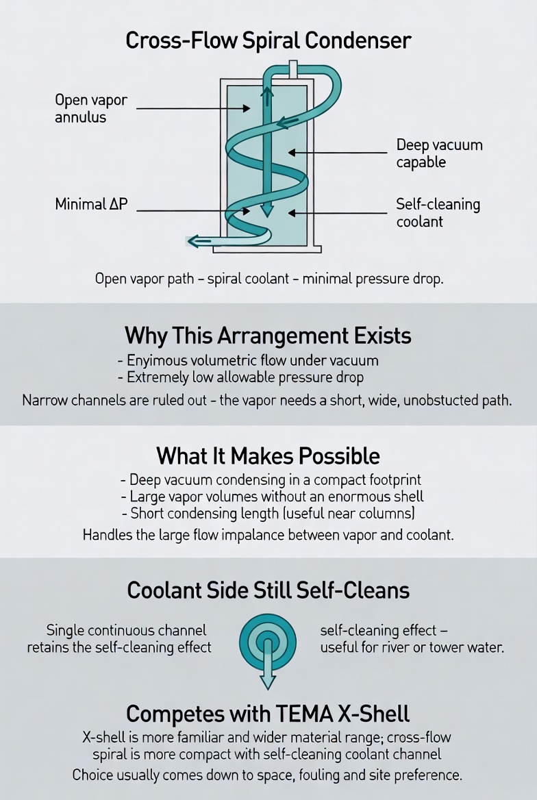
In a cross-flow spiral only one medium follows the spiral channel. The other passes straight through, parallel to the axis of the spiral element, in an open annular cross-section. The spiral channel is closed on both sides and carries the coolant; the crossflow fluid — the vapor — flows through the annulus around it.
Why this arrangement exists. Condensing under vacuum presents a specific problem: the volumetric flow is enormous and the allowable pressure drop is tiny. Those two constraints together rule out most compact exchanger geometries, because compactness normally means narrow passages and narrow passages mean pressure drop. The cross-flow spiral resolves it by giving the vapor a short, straight, unobstructed path with a very large flow area, while the coolant gets the tortuous spiral channel where turbulence and a good coefficient are wanted.
What that makes possible. Deep vacuum condensing in a compact unit. Very large vapor and gas volumes handled without an enormous shell. A short condensing section, which matters when the unit is mounted on or near a column, because it can allow a shorter overall structure. And because the vapor path is short and open, the arrangement copes well with the large flow imbalance that is typical between a condensing vapor and its coolant.
The coolant side still self-cleans. The spiral channel carrying the coolant retains the single-channel geometry and its scrubbing effect, which is useful when the cooling medium is river water, tower water or a process stream that fouls. The vapor side, being an open annulus, is inherently tolerant of what the vapor carries and easy to inspect.
Where it sits against the alternatives. For deep vacuum condensing the real competition is the TEMA X shell, which solves the same problem in a tubular format. The X shell is more familiar to most maintenance departments and offers a wider material range; the cross-flow spiral is more compact and brings the self-cleaning coolant channel. Both are legitimate and the choice usually comes down to space, fouling and what the site is comfortable maintaining.
See also single spiral for pressure duty, counterflow spiral for column mounting, and vacuum condensers.
Cross-Flow Spiral Configuration
The annular flow area is sized from the vapor volumetric flow and the pressure drop budget; the spiral channel is sized for coolant velocity and fouling tolerance.
Configuration
- Vapor Side: Open annular crossflow
- Coolant Side: Closed spiral channel
- Pressure Drop: Extremely low, vapor
- Section Height: Short condensing zone
Features
- Very large flow area
- Minimal vapor pressure drop
- Handles flow imbalance
- Coolant channel self-cleans
- Compact for large volumes
Typical Condensing Duty
- Deep vacuum condensing
- Vacuum distillation overheads
- Large gas volume cooling
- Ejector system condensers
- Dryer and deodorizer duty
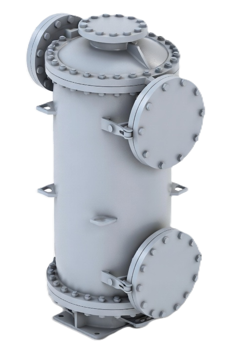
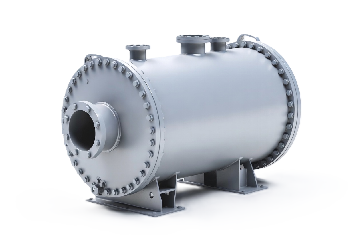
Cross-Flow Spirals on Vacuum Duty
The Pressure Drop Budget
On a vacuum condensing duty, pressure drop is not a performance metric to be optimized — it is a hard constraint set by the process. Whatever pressure is lost between the process and the condensing surface is pressure the process must operate at. If a vacuum dryer needs to run at a given absolute pressure and the condenser takes a significant fraction of that, the dryer never reaches its target and cycle times stretch on every batch thereafter.
This is why the crossflow arrangement is worth its complexity. Giving the vapor a straight path through a large open area means the pressure drop can be a small fraction of what a spiral or plate channel would impose. The design conversation starts with the allowable drop and works backward to the flow area required, rather than calculating drop at the end and hoping it is acceptable.
Noncondensables and Venting
Vacuum systems leak inward continuously, so a vacuum condenser always handles some noncondensable gas, and often a good deal of it. In an open annular vapor path, gas is carried along with the vapor rather than settling into dead pockets, which is an advantage over geometries with stagnant regions.
It still has to leave somewhere. The vent take-off needs to be positioned where the remaining gas concentrates after the bulk of the vapor has condensed, and it needs to connect to whatever vacuum-producing equipment serves the system. Sizing the condenser without knowing the expected gas load is guesswork, because gas loading changes both the required area and the achievable outlet condition.
Integration With Vacuum Equipment
A cross-flow spiral condenser rarely works alone. It sits in a system with ejectors, liquid ring pumps or dry vacuum pumps, and its job is to reduce the load those machines have to handle by removing the condensable fraction before it reaches them. Get the condenser right and the vacuum equipment is smaller, uses less energy and lasts longer.
That makes the condenser and the vacuum equipment a single design problem. Staging matters: an intercondenser between ejector stages and an aftercondenser at discharge is a standard arrangement, and the cooling medium is often routed through them in series. Where the process is being retrofitted or debottlenecked, understanding what the existing vacuum equipment can do usually determines what the new condenser needs to achieve.