1-805-484-2992
Quotes - Engineering - SalesSurface Steam Condensers
Condensing Turbine Exhaust Steam Under Vacuum
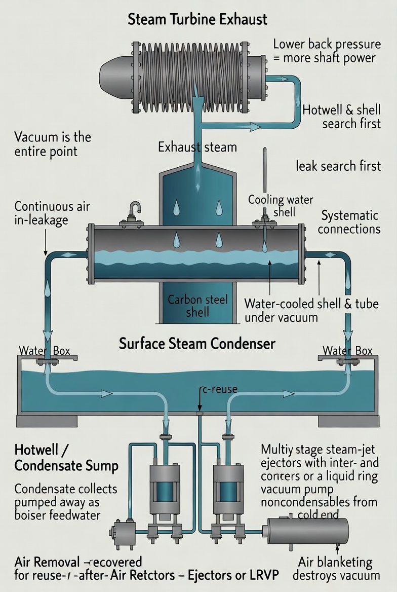
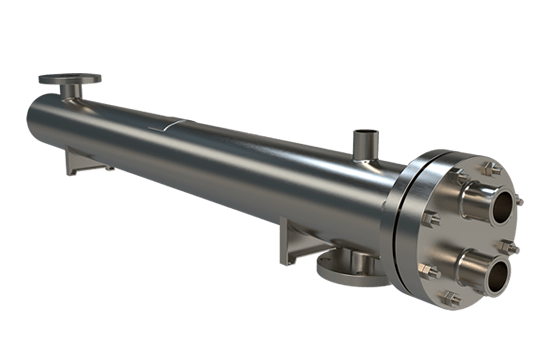
A surface steam condenser is a water-cooled shell and tube exchanger that condenses exhaust steam from a steam turbine at a pressure well below atmospheric. The vacuum is the entire point: turbine work output depends on the pressure ratio across the machine, so every inch of mercury of back pressure you avoid is recoverable shaft power. This is as true for a small turbine-driven pump or compressor as it is for a utility generating set, which is why these units appear far beyond power stations.
How the unit is arranged. The shell is typically fabricated carbon steel plate, stiffened for rigidity and fitted with intermediate plates that act as baffles to direct the condensing steam and support long tube runs against sag. Tubesheets at each end carry the tubes; water boxes on the tube side distribute cooling water, usually in one or two passes. At the bottom of the shell the condensate collects and drains, often into a sump or hotwell, from which it is pumped away for reuse as boiler feedwater. Fixed tubesheet TEMA construction is common, and water boxes are normally arranged to be removable without disturbing the water piping.
Air removal is not an accessory. A condenser operating under vacuum is surrounded by atmosphere at higher pressure, so air leaks inward continuously through valve glands, instrument connections, flanged joints and the turbine gland seals. Once inside, that air migrates to the condensing surface and forms a blanket, and blanketed surface does not condense. The result is a rise in shell pressure and a direct degradation of turbine heat rate.
Removing that air is the job of a steam-jet ejector set or a liquid ring vacuum pump, and frequently both: a hogger or starting ejector to pull the shell down from atmospheric quickly at startup, and running ejectors sized for steady-state in-leakage. Multi-stage ejector sets with surface inter- and after-condensers are standard practice, with cooling water routed through them in series. Vacuum tightness and flood testing during commissioning locate the leak paths before they become an operating mystery.
Where vacuum problems actually come from. When a condenser will not reach design vacuum, the cause is very often not the condenser. Valve glands on interconnecting piping, the vacuum breaker, atmospheric vent valves on the shell side, feedwater heater vents and drains, steam drain connections, makeup water connections and air evacuation connections are all routine in-leakage points. A systematic search through those beats adding surface area.
Connections worth having. Hotwell connections for ejector drain, condensate outlet, level control bypass, startup fill, gauge glass and high-level alarm; shell connections for pump vent, vacuum gauge, atmospheric relief and the turbine exhaust inlet; water box vents and drains. Specifying these at the start costs nothing and saves a great deal of retrofit work later.
Where cooling water is short, an air-cooled condenser can serve the same duty, accepting a larger installation and performance that tracks ambient temperature. Evaporative arrangements sit between the two. Related pages: vacuum condensers and vent condensers.