
1-805-484-2992
Quotes - Engineering - Sales| PRODUCT | STYLE | ARRANGEMENT | TYPICAL DUTY |
| Air Cooled Condenser | V-Bank / A-Frame | Sloped Bundles | Steam & Large Vapor |
V-Bank and A-Frame Condensers
Sloped Bundles for Gravity Drainage and Maximum Face Area
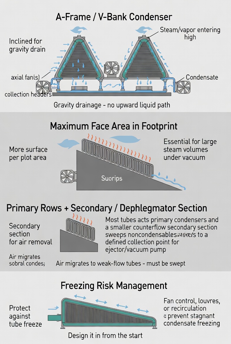
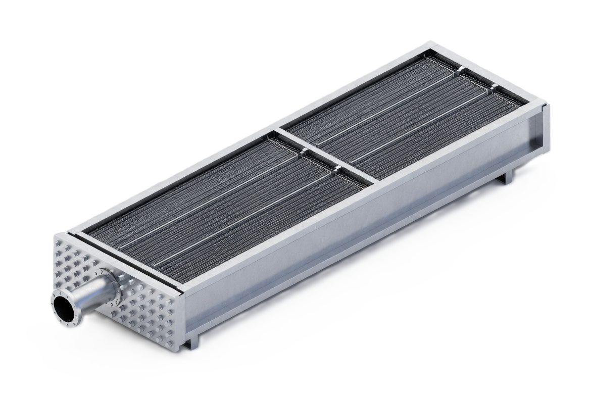
An A-frame condenser stands two finned tube bundles against each other like a roof, with the fan beneath blowing air up through both. A V-bank inverts the geometry. Either way the bundles are inclined rather than flat, and that inclination is doing two jobs at once.
Gravity does the drainage. Steam entering a header at the apex condenses as it travels down the sloped tubes, and the condensate runs downhill to a collection header at the bottom. There is no pass that asks liquid to climb, no low point where it can pool, and no reliance on vapor velocity to drag liquid along. For a duty where the condensate rate is enormous — and turbine exhaust condensing produces a great deal of water — that gravity path is not a refinement, it is the enabling feature.
Face area in a given footprint. Volumetric flow of steam at condenser vacuum is extraordinary. A flat bundle large enough to condense it would occupy an impractical amount of plot. Standing the bundles at an angle presents far more heat transfer surface to the air per square foot of ground, which is what makes an air cooled steam condenser buildable at all.
Noncondensable removal is critical here. Air cooled steam condensers operate under vacuum, so air leaks inward continuously. In a multi-cell A-frame with many parallel tube rows, that air migrates to wherever flow is weakest and blankets the surface there. The standard arrangement handles this deliberately: most tubes run as primary condensing rows, and a smaller set run as a secondary or dephlegmator section arranged counterflow, deliberately sweeping noncondensables to a defined collection point where an ejector or vacuum pump removes them. Without that arrangement the gas simply accumulates and the condenser loses capacity.
Freezing is the cold-weather hazard. A tube that condenses all of its steam before the outlet has stagnant condensate in the remaining length, and stagnant condensate in freezing ambient air will freeze, which can split a tube. Managing this requires fan control, sometimes reverse-flow fans, adjustable louvres, warm air recirculation and attention to how the secondary rows are arranged. It has to be designed in from the start.
See horizontal fin fan for smaller process duty, draft arrangements for the fan decision, and surface steam condensers for the water cooled equivalent.
V-Bank and A-Frame Configuration
Cell count, slope angle, fan size and the primary-to-secondary row split are all set by the vapor volume, the site ambient design case and the freeze protection required.
Configuration
- Arrangement: A-frame or V-bank
- Bundles: Inclined, sloped drain
- Rows: Primary and secondary
- Gas Removal: Ejector or vacuum pump
Features
- Gravity condensate drain
- Very large face area
- Multi-cell modular build
- Dephlegmator row option
- Freeze protection design
Typical Condensing Duty
- Turbine exhaust steam
- Air cooled condensers
- Large vapor volumes
- Vacuum steam condensing
- Water-scarce power sites
Air Cooled Steam Condensing in Practice
Why the Secondary Row Exists
This is the detail that distinguishes a properly engineered air cooled condenser from a large finned bundle. In the primary rows, steam enters at the top and condenses as it flows down. If all rows worked that way, noncondensable gas would concentrate at the bottom of every tube, where it would sit and blanket surface with nothing to sweep it out.
The secondary rows — often called dephlegmator or reflux rows — are plumbed so steam enters from the bottom header and flows upward against the draining condensate. That counterflow deliberately drives the noncondensables to the top, where they are collected and removed by the vacuum equipment. The gas has a defined destination instead of an accidental one. It is also the section most at risk of freezing, which is why its control gets particular attention.
Ambient Dependence and Turbine Output
An air cooled steam condenser ties plant output directly to the weather. Back pressure follows ambient dry bulb temperature, and turbine output follows back pressure, so a hot afternoon costs real megawatts. The design case is generally chosen from site temperature statistics as an economic optimization rather than an absolute worst case, accepting some hours of derated output each year in exchange for a smaller and cheaper condenser.
Wind matters too, and it is often underestimated. Cross-winds across a large elevated ACC structure can starve upwind fans and drive hot plume air back into the inlet, effectively raising the inlet temperature. Wind walls, screens and careful attention to structure height and orientation all form part of the design.
Cleaning and Long-Term Performance
The air side of a large ACC is a very large surface exposed continuously to whatever the site atmosphere carries. Over time, fouling between fins reduces air flow and insulates the tubes, and because the change is gradual, the resulting rise in back pressure is easy to attribute to something else.
Periodic washing is normal maintenance, and the structure should be designed so it is practical: access platforms, adequate spacing between cells and consideration of how wash water drains. A condenser that is difficult to wash will not be washed on schedule, and the cost of that shows up as a permanent increase in heat rate rather than as a maintenance line item.