
1-805-484-2992
Quotes - Engineering - Sales| PRODUCT | STYLE | MOUNTING | CONDENSATE |
| Condenser | Counterflow Spiral | Column or reactor top | Gravity, subcooled |
Counterflow Spiral Condensers
Column-Mounted Condensing With Built-In Subcooling
The counterflow spiral was developed for a specific job: to be mounted vertically onto a column or reactor and do away with the separate condenser entirely. Vapor enters at the top of the unit and condenses on the spiral plates. The condensate falls under gravity to a collection point at the bottom. The cooling medium flows in a spiral path from the periphery toward the center, and condensate and uncondensed gas are discharged separately.
What mounting on the column eliminates. The advantage is not primarily thermal — it is everything the arrangement removes. No large-diameter vapor pipework running from the column top to a remote condenser. No structural steel to support that condenser. Often no reflux drum, no reflux pump and no return line. Because the connection size for incoming vapor can be matched to the column outlet, the unit sits straight on top with no piping work at all. On a hazardous or corrosive service, the reduction in flanged joints and rotating equipment is a safety benefit as much as a cost one.
Subcooling comes free. This is a genuinely useful characteristic of the geometry. The outer turns of the spiral run countercurrent to the coolant, so condensate traveling outward meets progressively colder surface and is subcooled on its way to the collection point. A separate subcooling exchanger is often unnecessary. The spiral flow in those outer turns also gives better heat and mass transfer than pure crossflow would, so the arrangement is thermally efficient as well as compact.
Where it fits. Counterflow spirals are best suited to vapor mixtures at moderate pressure containing small to moderate amounts of noncondensable gas. That describes a great many column overheads, stripping column condensers and reactor reflux duties. Because the unit is efficient and short, the column itself can sometimes be shorter and smaller in diameter, and when that happens the saving in infrastructure is larger than any difference in exchanger price.
The honest limitation. Operation at very low absolute pressure is seldom practical in this configuration, because pressure drop through the outer spiral turns becomes excessive. That is exactly the gap the cross-flow arrangement exists to fill. If your duty is deep vacuum, that is the page to read.
Related: single spiral, reflux condensers and dephlegmators.
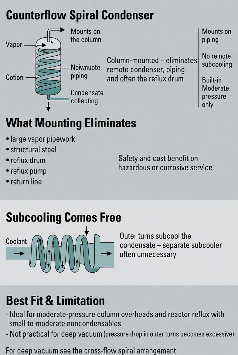
Counterflow Spiral Configuration
The unit is sized around the vapor load, the noncondensable fraction and the amount of subcooling wanted, with the vapor connection matched to the column outlet.
Configuration
- Mounting: Direct on column top
- Vapor Entry: Top of unit
- Coolant: Periphery to center
- Outlets: Condensate and gas separate
Features
- No separate support steel
- No large vapor pipework
- Built-in subcooling
- Separate gas discharge
- Shorter column possible
Typical Condensing Duty
- Column top condensers
- Reflux condenser duty
- Stripping column overheads
- Reactor vapor condensing
- Solvent recovery columns
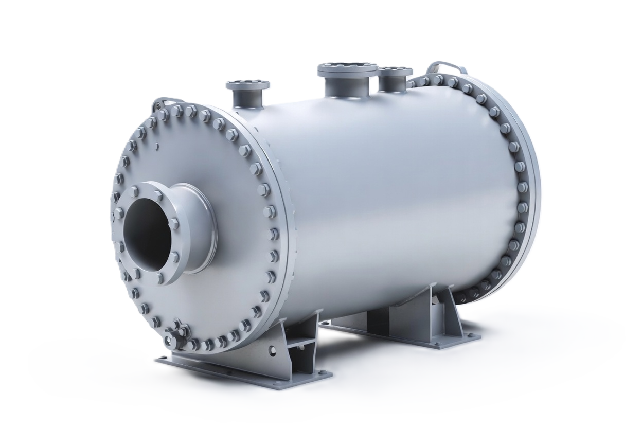
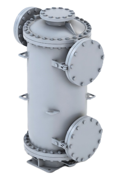
Column-Mounted Condensing
Counting the Real Saving
The exchanger price is the smallest part of this decision. A remote condenser arrangement needs a large-diameter vapor line from the column top, sized for low pressure drop and therefore expensive; structural steel to carry the condenser at elevation; a reflux drum with its level instrumentation, relief protection and nozzles; a reflux pump with its motor, seals, spares and power; and return piping back up to the column.
Mounting the condenser directly on the column removes most of that list. When the comparison is made properly — installed cost including steel, piping, instrumentation and rotating equipment rather than exchanger price alone — column-mounted arrangements frequently win by a wide margin. They also remove a pump and a set of flanged joints from a service that may be hazardous, which has a value that does not appear in the capital estimate at all.
Control Considerations
The trade-off is the same one that applies to any condenser generating reflux internally. A reflux drum holds inventory, which allows reflux flow to be measured and manipulated directly and buffers the column against upsets in coolant temperature, vapor rate or inert loading. A column-mounted condenser has very little holdup, so reflux is inferred rather than measured and disturbances propagate into the column immediately.
For many columns that is entirely acceptable, and the equipment saving is worth it. For a column with tight product specifications, frequent rate changes, or a control scheme that depends on manipulating reflux independently, it may not be. This is a question worth settling early with the process engineers rather than discovering during commissioning, and we would rather raise it at quotation than let it become a surprise.
Noncondensables and Separate Discharge
One useful feature of the counterflow spiral arrangement is that condensate and uncondensed gas leave through separate outlets. That matters because a column overhead almost always carries some inert or light-ends fraction, and it has to go somewhere other than into the reflux.
Separate discharge means the gas can be routed to vent treatment, to a downstream vent condenser for further recovery, or to a vacuum system, without dragging condensate with it or requiring a separation vessel. The configuration is well suited to vapor mixtures carrying small to moderate noncondensable loads for exactly this reason. Where the gas fraction is large, a dedicated vent condenser stage downstream is the usual addition.