
1-805-484-2992
Quotes - Engineering - Sales| PRODUCT | STYLE | TEMA TYPE | BUNDLE |
| Vapor Condenser | U-Tube | BEU / AEU / BKU | Removable |
U-Tube Condensers
Free Thermal Expansion With a Removable Bundle
A U-tube exchanger has one tubesheet. Tubes enter it, run the length of the shell, bend through 180 degrees and return to the same tubesheet. That single geometric decision solves two problems at once, which is why U-tube bundles are so common in condensing service.
Thermal expansion stops being a design problem. Because each tube is anchored at one end only and free at the bend, every tube can expand and contract independently. There is no differential expansion load between shell and bundle to accommodate and no expansion joint to specify, maintain or worry about. This makes U-tube construction the most tolerant standard configuration for large temperature differences and for thermal shock — and condensing duty produces plenty of both. Saturated steam meeting cold cooling water is a large temperature difference by definition, and startup, trip and blowdown transients on a condenser can be abrupt.
The bundle comes out. With a single tubesheet and no rear head to unbolt, the bundle withdraws from the shell as one assembly. The shell interior and the outside of the tubes can then be inspected, hydroblasted or mechanically cleaned. On condensing duty where the vapor is on the shell side — which is most large condensers — that access is the difference between a unit you can maintain and one you can only chemically flush and hope.
The U-bend is the trade-off. Straight tubes can be brushed or lanced end to end. A U-bend cannot, at least not easily, so tube-side mechanical cleaning is limited. This makes U-tube construction a poor choice when the fouling fluid is inside the tubes, and a good one when the tube side is clean — treated cooling water, clean steam, refrigerant. The general rule is to put the clean fluid in the tubes of a U-tube exchanger, which is the reverse of the usual advice for straight-tube units.
Why U-tube dominates knock-back and reflux service. Vertical U-tube units with removable bundles are the standard construction for knock-back and cold trap condensers. Vapor rises into the shell, contacts the cooled tubes, condenses and drains from the shell bottom. Because there is only one tubesheet and it sits at the top, the shell below is unobstructed by any rear head, which allows an extended shell section to collect condensate separately from the bundle. Nothing about that arrangement works as neatly with a floating head or a fixed tubesheet.
Related: fixed tubesheet for clean, low-cost duty, floating head where straight tubes must also come out, and reflux condensers for the application.
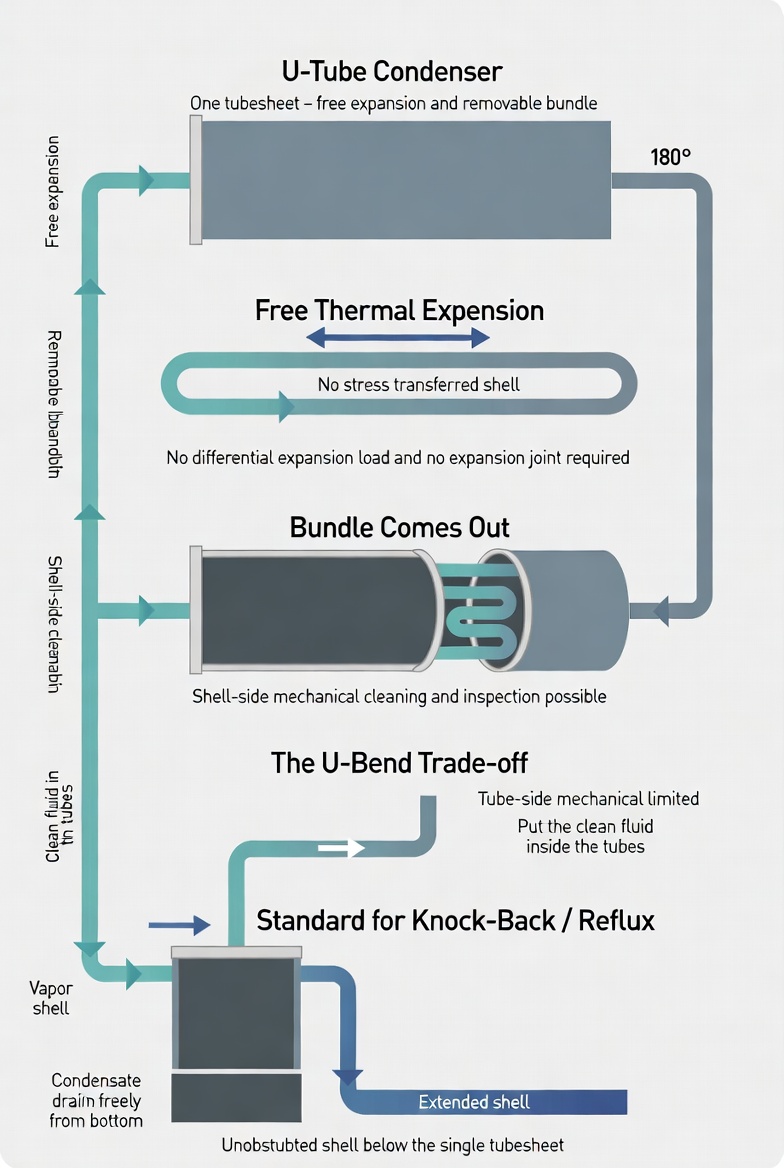
U-Tube Condenser Configuration
Typical arrangement for condensing duty. Tube layout, baffle style and bend radius are all set by the vapor characteristics and the cleaning method.
Configuration
- TEMA Types: BEU, AEU, BKU
- Bundle: Fully removable
- Expansion: Free, no joint
- Vapor Side: Shell or tube side
Features
- Independent tube expansion
- Best thermal shock rating
- Single tubesheet only
- Shell side mechanically clean
- Economical TEMA design
Typical Condensing Duty
- Knock-back condensers
- Reflux and cold traps
- Steam to water condensing
- Sanitary and CIP duty
- Large temperature crosses
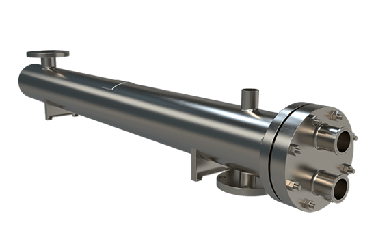
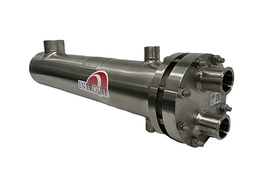
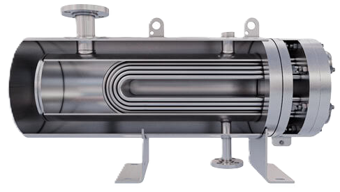
U-Tube Condensers in Service
Which Fluid Goes in the Tubes
This decision matters more on a U-tube exchanger than on any other configuration, because the asymmetry is severe. The shell side can be mechanically cleaned by pulling the bundle. The tube side cannot be mechanically cleaned properly, because of the bend. So the fouling fluid belongs on the shell side and the clean fluid in the tubes.
For condensing service that usually works out conveniently. Cooling water — treated, filtered and reasonably predictable — goes in the tubes. Process vapor, which may carry solids, polymerize or deposit heavy ends, condenses on the shell side where the surface can be reached. It is worth stating explicitly at the inquiry stage which stream is the dirty one, because it can flip the configuration decision entirely.
Thermal Shock and Cycling Duty
Condensers see transients that steady-state datasheets do not describe. A unit that trips loses vapor flow instantly while cooling water keeps circulating. A unit starting up sees hot vapor arrive at a bundle sitting at ambient. Batch service cycles through this repeatedly, sometimes several times a day.
Because each U-tube expands independently, the bundle absorbs those transients without transmitting load into the tubesheet joints or the shell. That is why U-tube construction is specified for severe thermal shock service, and why it is the default choice on batch reactor and batch distillation condensers where cycling is inherent to how the plant runs.
Sanitary and High-Purity Variants
U-tube bundles are widely used in sanitary and pharmaceutical condensing, generally in vertical orientation. The removable bundle assists inspection and validation, and the single tubesheet means fewer joints in the product path. Where product must be protected from the utility fluid, the same geometry is built with a double tubesheet and a vented interspace, so a joint leak drains to a visible point rather than crossing streams. Polished 316L wetted surfaces, sanitary clamp connections and a shell sloped to a low-point drain complete the arrangement.
Cost Position
U-tube bundles sit between fixed tubesheet and floating head on cost, and closer to the fixed tubesheet end. Forming and bending tubes adds labor, and the bend radius on the innermost tubes sets a minimum bundle centerline spacing that slightly reduces tube count for a given shell diameter. Against that, there is no expansion joint, no floating head assembly and no second tubesheet. In practice a U-tube bundle is an economical way to obtain a removable bundle, which is why it appears so often once shell-side access is a requirement.