
1-805-484-2992
Quotes - Engineering - SalesContainment-First Condensers for Toxic Vapors
With a toxic vapor, the question is not only how much the condenser recovers but what it does when something goes wrong. Phosgene, chlorine, hydrogen sulfide, acrylonitrile, benzene or a potent pharmaceutical intermediate can harm people at very low concentrations, so a tube leak, a weeping flange or a drain opened for sampling becomes an exposure event. Condensing these vapors takes them out of the vent gas, but it also creates a liquid inventory that has to be contained, monitored and sent somewhere safe. The design starts from leak paths and finishes with heat transfer.
- Leak Direction: Set coolant pressure above or below the process side on purpose, and know where a tube failure sends the toxic fluid.
- Double Barrier: Double-tubesheet construction puts an inspectable gap between process and coolant, so a leak shows before it crosses over.
- Leak Detection: Monitor coolant return or the tubesheet interspace with an analyzer suited to the compound, not just a pressure gauge.
- Closed Drains: Condensate should run to a closed receiver vented back to treatment, never to an open funnel or trench.
- Joint Count: Every flange and gasket is a potential release point; welded connections and fewer nozzles shorten the leak list.
- Decontamination: Plan how the unit is flushed and purged before anyone opens it, including rinse and nitrogen connections.
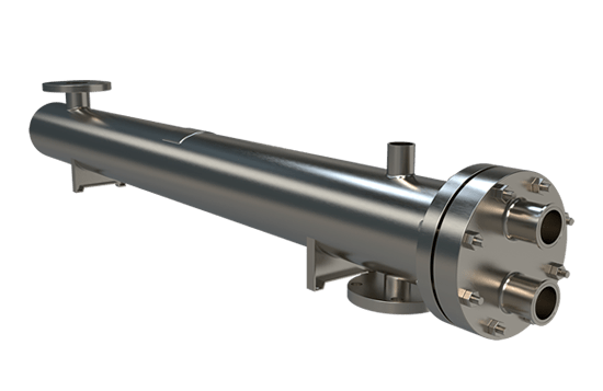
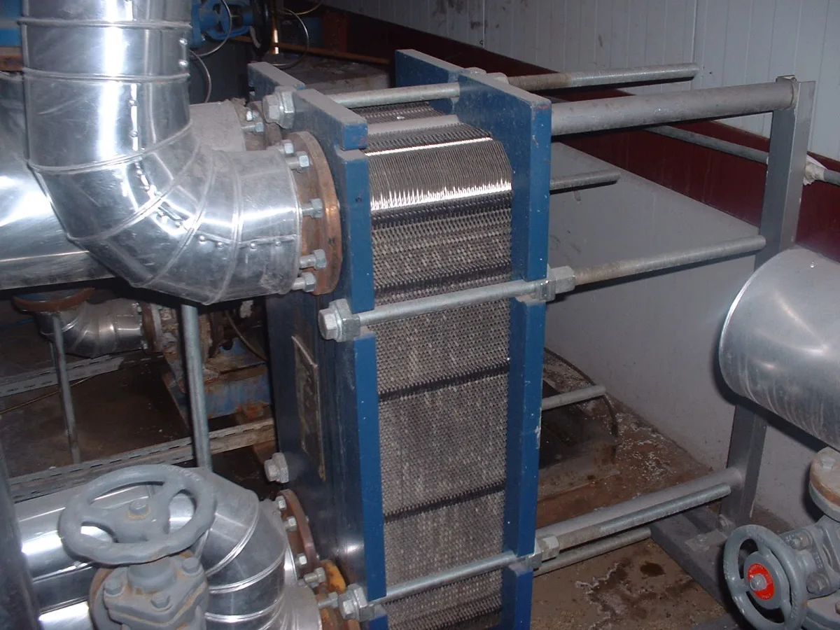
Where Toxic Condensate Goes, and How It Gets There
A toxic-service condenser should be designed as one piece of a closed system, from the vapor inlet through to the vessel that receives its condensate and the vent that leaves that vessel. Heat transfer on these duties is rarely difficult; the engineering effort goes into making every route out of the equipment either sealed or monitored.
Start with the pressure hierarchy. For most toxic vapors, cooling water should run at higher pressure than the process so a failed tube leaks water inward rather than toxic material into the plant water system. Where the process cannot tolerate water, a dedicated closed glycol loop with its own analyzer becomes the barrier, keeping any leak inside a small sampled circuit instead of a cooling tower and its drift.
A Fixed Tubesheet exchanger suits this service well: welded tube-to-tubesheet joints, an all-welded process side, and the option of a double tubesheet whose vented interspace is piped to a detector. A Welded Plate exchanger offers the lowest holdup and a fully welded pack, which minimizes inventory, but an internal leak is harder to locate and the plates cannot be inspected the way a tube bundle can; pair it with a closed, monitored coolant loop.
Bring the compound's toxicity data and exposure limits, the plant's containment standard, whether a closed coolant loop is available, and how the receiver and its vent are arranged.
Exposure limits
Compound toxicity data and the plant containment standard
Coolant loop
Whether a dedicated closed cooling circuit is available
Drain destination
Closed receiver, its vent path and downstream treatment
Opening procedure
How the unit is cleared before maintenance access
Containment
Designed In From the Start
1.
Leaks Found Early
A double tubesheet collects any tube-joint leak in a vented interspace piped to a detector, so a failure appears as an alarm instead of as toxic material discovered later in the cooling water.
2.
Isolated Coolant
Running on a dedicated closed glycol or tempered-water loop keeps any leaked compound inside a small, sampled circuit rather than spreading it through the plant cooling tower.
3.
Small Inventory
Low holdup and short drain runs limit how much toxic liquid sits in the equipment at any moment, which reduces the release quantity used in the hazard assessment and emergency planning.
Containment questions
When a tube joint leak in either direction would be an exposure event or a runaway reaction, and when the plant wants that leak announced by an alarm rather than discovered in the cooling water. Phosgene, chlorosilanes and anything that hydrolyzes violently qualify in both directions. The construction adds a second tubesheet at each end with a vented gap between, typically a few inches, and raises the price of a Fixed Tubesheet unit by a noticeable fraction and its length by several inches.
Pipe the interspace vents to a sight glass or a detector suited to the compound and check them on rounds. Where cost rules it out, a closed glycol loop with its own analyzer and a tube-side leak test at every outage is the fallback, but it finds the leak later than a double tubesheet would.
Yes in most toxic services, by enough margin that water leaks into the process rather than toxic material into the water, and the margin must hold at the pump's lowest running point, not only at design. A plant tower loop at 40 psig against a vent condenser near atmospheric pressure gives an easy hierarchy. It gets harder on a pressurized process or when the water pump cycles, so put a low differential pressure alarm on the pair.
The exception is a process that can not tolerate water at all: phosgene forms HCl and carbon dioxide, and chlorosilanes form silica and HCl. There the barrier becomes a dedicated closed glycol or tempered-water loop with its own small volume, a sampling point and an analyzer, so that whichever way a leak runs it stays inside a circuit someone is watching.
Through a closed-loop sampler bolted onto the receiver, in which purge flow circulates back to the receiver and a sealed bottle fills by needle through a septum, with nothing open to the room at any step. The design detail that gets missed is the purge: a sampler on a dead leg draws stale liquid, and the operator opens it again to get a representative sample.
Place the sampling loop on the receiver recirculation line so the first draw is fresh, and vent the bottle headspace back to the receiver vent and on to treatment. Operators should still wear the protection the task hazard analysis calls for, since the bottle has to be carried and opened in a fume hood. Record each sample event with the operator's name and the receiver level.
Drain, flush, purge, then test, in that order, with every step through hard-piped connections and a work permit that names the acceptable residual concentration. Drain to the closed receiver and confirm by level that the shell or tubes are empty. Flush the process side with a solvent that dissolves the compound or, for water-compatible materials, with water, pushing the flush to the receiver as well.
Purge with nitrogen from the end opposite the drain until a gas test at the drain reads below the limit; a sulfide compound may need a caustic wash step before the nitrogen. Only then break the first flange, and do it at the lowest point with a drip tray. Nozzles for flush and purge should be on the drawing from the start, since adding them later to a toxic-service unit means another entry.