
1-805-484-2992
Quotes - Engineering - SalesSide Draw Vapor Condensing
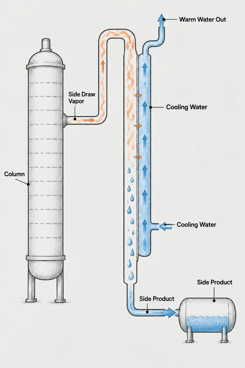
A side draw takes product from partway up a fractionation column rather than from the top or bottom. Most side draws are withdrawn as liquid from a draw tray, but where a vapor side draw is taken, usually in the stripping section so the product carries fewer heavy impurities, it needs its own condenser. That vapor is heavier and condenses hotter than the overhead, its composition is set by the draw tray rather than the top of the column, and its flow is usually a fraction of the overhead. Each of those changes the condenser.
- Hotter Condensing: A side draw condenses well above the overhead temperature, so tempered water or heat recovery can replace cooling water as the heat sink.
- Draw Composition: The vapor matches the draw tray, not the top; it holds intermediate boilers with traces of both lighter and heavier neighbors.
- Rate Control: Draw rate is set by a control valve on the vapor line or the liquid outlet, and the condenser must not add backpressure that fights the controller.
- Heat Recovery: Because the vapor condenses hot, the duty can preheat feed or warm another stream before a trim cooler brings the liquid to storage.
- Pressure Matching: The condenser runs near draw tray pressure, above the top pressure, so nozzles and lines must respect the small differential available.
- Product Routing: The condensed side draw is an intermediate product in its own right, usually sent to its own tank or side stripper rather than back to the column.
A Separate Product With Its Own Condenser
A side draw condenser serves a different product than the overhead condenser and should not be treated as a smaller copy of it. Vapor drawn from a mid-column tray is richer in intermediate-boiling components, so its condensing temperature is higher and its condensing range may be broader. That gives the designer options the overhead lacks: the duty can often go to tempered water, boiler feedwater or a process stream that needs heating, with a small trim cooler afterward.
The difficulty is hydraulic. A vapor side draw leaves the column at draw tray pressure and must reach the condenser and then its receiver without much loss, because the driving force between the draw tray and the downstream system is limited. A condenser that adds unexpected pressure drop reduces the draw rate the controller can achieve, and the intermediate product starts appearing in the overhead or bottoms instead.
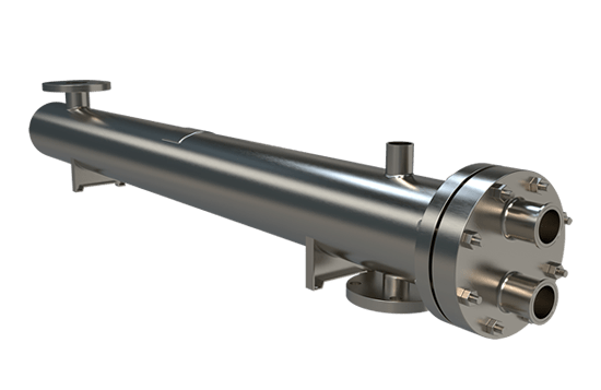
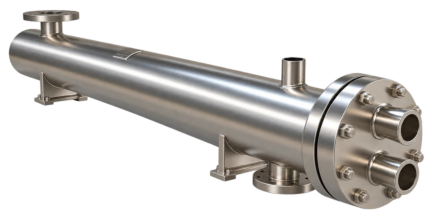
Fixed Tubesheet shell-and-tube construction with vapor on the shell side is generally the best fit, because shell-side condensing gives low pressure drop and straight tubes accept whatever coolant the heat-recovery scheme uses. A U-Tube design is useful when the side draw condenses hot enough against a cool process stream that differential expansion becomes significant, or when the bundle has to come out for cleaning of a fouling intermediate; keep the tube-side fluid the cleaner one in that case.
For a quote, provide the draw tray pressure and temperature, the vapor draw rate and composition, the pressure available at the receiver, the intended heat sink, and the liquid temperature the downstream tank or stripper needs.
Draw tray
Tray pressure, temperature and vapor composition at the draw
Draw rate
Normal and maximum side-draw vapor flow
Heat sink
Tempered water, feed preheat or another stream to warm
Receiver pressure
Pressure at the tank or stripper downstream
Mid-Column Product,
Condensed on Its Own Terms
1.
Heat Put to Use
Because a side draw condenses hotter than the overhead, its latent heat can preheat feed or warm a utility stream, cutting both cooling-tower load and reboiler steam.
2.
Draw Rate Protected
Low shell-side pressure drop leaves the draw control valve enough differential to hold product rate, so intermediate components stay in the side product and out of the overhead.
3.
Product-Ready Liquid
Condensing and trim cooling deliver the side product at the temperature its tank or side stripper expects, without flashing at the receiver or losing light material through the tank vent.
Side draw design questions
A vapor side draw is chosen when the intermediate product must be free of high boilers, because vapor leaving a tray carries far less of the heavy components than the liquid sitting on that tray. Picture a column splitting a three-component solvent blend where the middle cut goes back to a customer with a tight color and residue spec. A liquid draw from the same tray would carry dissolved heavies along, and a side stripper would be needed to clean it up. The vapor draw skips the stripper but hands the job to a condenser, which must run at a pressure only slightly below the tray. Your decision usually comes down to whether the plant can afford the pressure budget for a condenser and receiver, or would rather pump a liquid draw and accept a polishing step afterward.
Yes, and the recovery is often worth more per square foot than any other condenser on the column, because the side draw condenses at a temperature high enough to heat something useful. A draw condensing at 250 F can warm column feed from 120 F to 200 F, and every BTU moved there is a BTU the reboiler does not supply and the cooling tower does not reject. Rate the recovery exchanger on the heat sink's own flow and temperature swing, then size a trim cooler on plain cooling water to bring the product to tank temperature. The common mistake is letting the recovery stage set the final liquid temperature; when feed rate drops, the product arrives hot and flashes at the receiver. Keep the trim cooler in control of the outlet.
Excess pressure drop starves the draw control valve of differential, so the measured draw rate drifts below setpoint and cannot be recovered by opening the valve further. On the board it shows up as a valve pinned at 100 percent while the flow transmitter reads low. In the lab, the intermediate component climbs in both the overhead and the bottoms within a few hours. Add up every loss between the draw tray and the receiver: the vapor line, the condenser inlet nozzle, the shell-side pass, and the condensate leg. If that total is more than about half the differential the tray can give, the condenser is the first place to look for savings, since shell-side condensing with a wide inlet and a short vapor path can cut its share to a fraction of a psi.