
1-805-484-2992
Quotes - Engineering - SalesKnock-Back Duty on Column Overheads
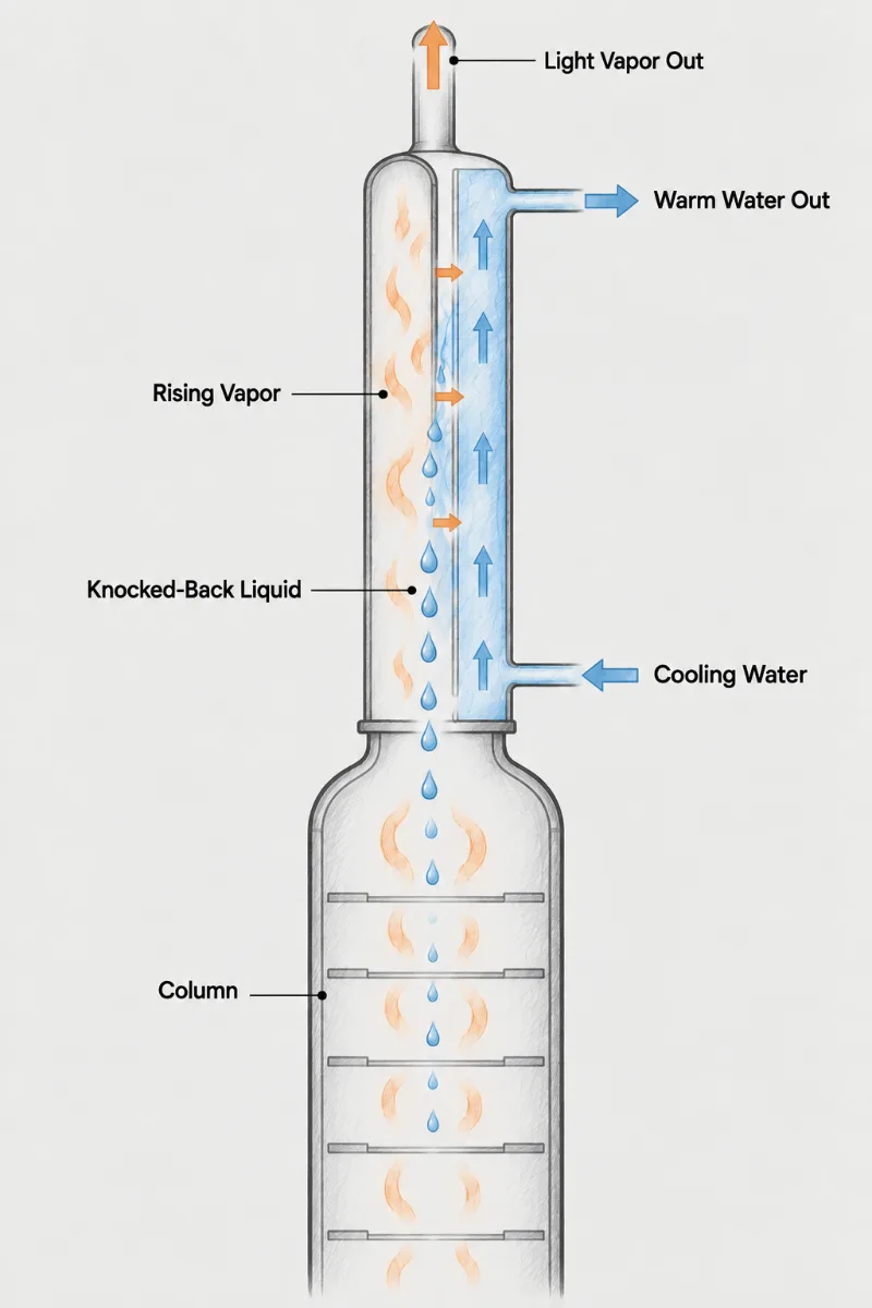
On a column, a knock-back condenser sits on the overhead vapor line and condenses only part of what leaves the top tray. That liquid falls straight back as reflux; the vapor that gets through goes on to a product condenser and becomes distillate. The split between the two is the reflux ratio, so the knock-back unit is not just removing heat, it is setting the separation. Unlike a total condenser feeding a drum, there is no valve or pump to trim reflux after the fact. Coolant temperature and flow do that job, which changes how the unit is sized and controlled.
- Reflux Ratio: Whatever condenses here becomes reflux, so the rating must state the target ratio at design boil-up and at the lowest rate the column runs.
- Partial Duty: Only part of the overhead condenses in this unit; area is sized to a vapor split, and oversizing drives reflux higher than the column needs.
- Coolant Lever: A tempered water loop with adjustable inlet temperature gives finer reflux control than throttling cold water, which swings tube-wall temperature sharply.
- Rectifying Effect: Rising vapor scrubbed by falling condensate inside the tubes leaves slightly richer in the light key, adding a little separation the column gets for free.
- Top Pressure: Every bit of pressure lost across the knock-back raises column top pressure and the bubble points below it; vacuum columns may allow only a few torr.
- Product Condenser: The downstream unit takes whatever vapor passes, so both condensers are rated as a pair across the full range of expected reflux ratios.
Setting Reflux Ratio with Heat Removal
What sets the reflux ratio on a column fitted with a knock-back condenser? The duty of the knock-back itself. Whatever condenses in its tubes drains back to the top tray; whatever does not becomes distillate in the condenser downstream. A column that needs a reflux ratio of three to one at design boil-up therefore needs a knock-back that condenses three quarters of the overhead, and no more, at the coolant conditions available on the day. Too little area starves the column of reflux and overhead purity falls. Too much area condenses nearly everything, distillate rate collapses, and operators throttle coolant until the shell side runs warm and uneven.
Columns also run across a wide range of boil-up, so the knock-back is rated at minimum and maximum vapor rate, not only at design. At high boil-up the vapor velocity in the tubes approaches the point where falling condensate is held up. The symptom is a pressure surge at the column top and liquid carried forward into the product condenser, which appears in the lab as off-spec distillate. Tube diameter, tube count and the inlet tube-end detail are chosen against that limit before the area is finalized.
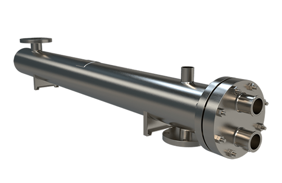
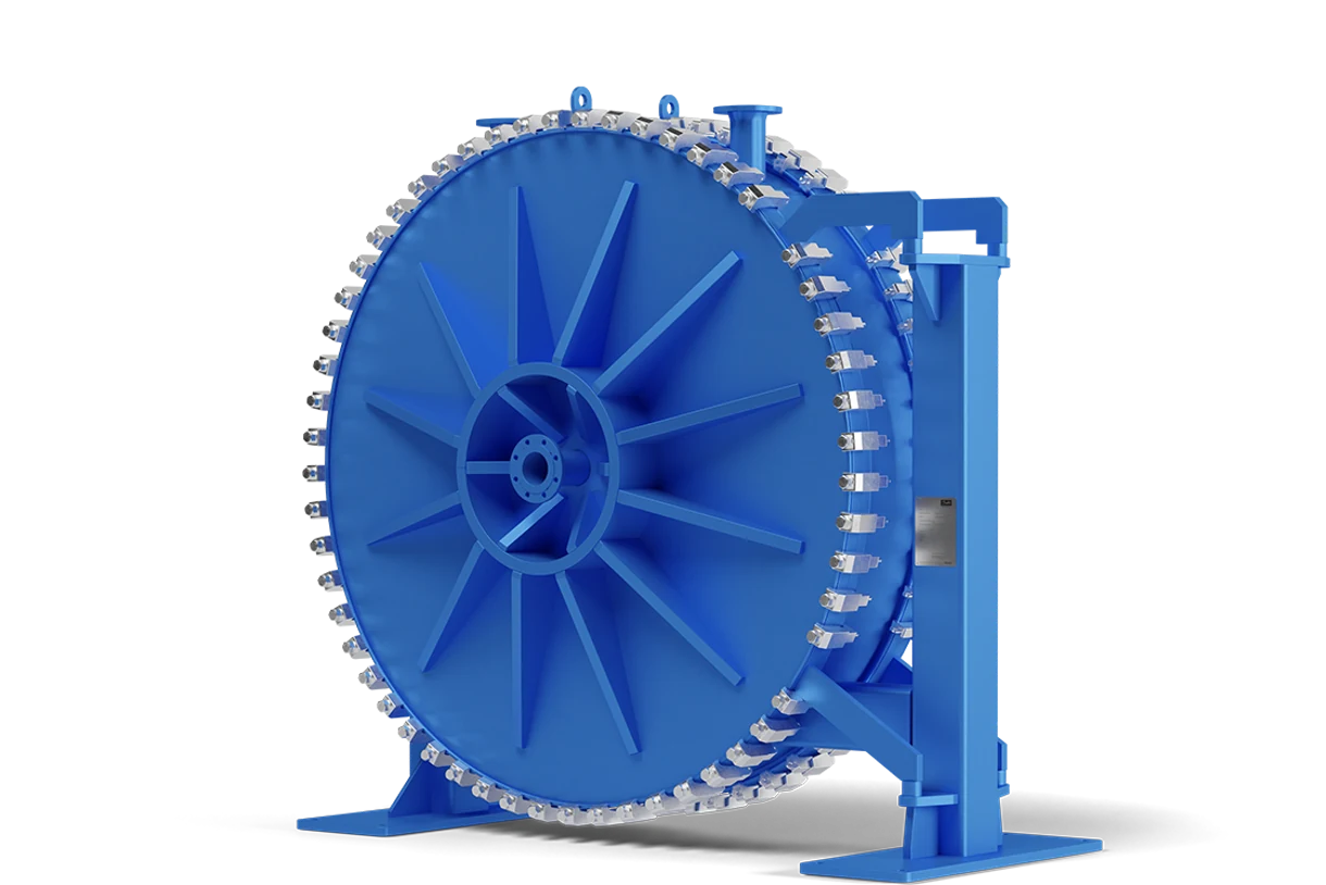
A vertical Fixed Tubesheet exchanger with vapor in the tubes and coolant on the shell side is the standard construction here: straight tubes drain, the inlet face is uniform, and alloy choice runs from carbon steel for hydrocarbons to 316L or duplex for chlorinated or acidic overheads. A Counterflow Spiral does not belong on the column head, because its spiral channels cannot return liquid against rising vapor. It earns its place downstream as the product condenser or distillate cooler, where a true countercurrent path gives a close approach in little plot space.
For a quote, have the overhead vapor rate and composition across the boil-up range, the target reflux ratio, column top pressure and the drop the trays can tolerate, the coolant source and whether a tempered loop exists, and the size of the column-top nozzle.
Reflux target
Desired reflux ratio at design and at minimum boil-up
Overhead vapor
Top-tray vapor rate, composition and temperature across the range
Column pressure
Head pressure and the drop the trays will tolerate
Downstream unit
Whether the product condenser exists or is quoted alongside
Reflux Set
by Coolant, Not by a Pump
1.
Fewer Moving Parts
Gravity return replaces the reflux drum, reflux pump and flow control valve, which removes a seal leak point and frees the floor space those items would occupy beside a small or mid-size column.
2.
Steadier Top Composition
Reflux condensed directly above the top tray returns at its bubble point, so there is no subcooled stream from a drum disturbing tray temperature, and overhead purity follows the coolant setpoint closely.
3.
Matched Condenser Pair
Rating the knock-back and the product condenser together lets duty shift between them as reflux ratio changes, so neither unit is left badly oversized at one end of the operating range.
Reflux and flooding questions
Change the coolant inlet temperature to the knock-back, because its duty, and therefore the share of overhead it condenses, follows the temperature difference between vapor and tube wall. On a column boiling at 230 F, raising tempered water from 120 F to 150 F cuts the driving force by about 27 percent and lowers reflux by a similar share. Throttling raw cooling water to get the same effect leaves the shell side half-starved, with the outlet end running hot and scaling. If the column has no tempered loop, a small recirculation pump and a three-way mixing valve on the existing cooling water make one; that is cheaper than the reflux drum it replaces.
On many small and mid-size columns it can, provided the column top can carry the condenser's weight and the trays can tolerate the added pressure drop. Check three things before committing. First, the headroom: a vertical knock-back for a 30-inch column may stand 8 to 12 feet above the top nozzle. Second, the top nozzle and head loading with the shell full of water during hydrotest. Third, the pressure drop at maximum boil-up, which lands on top of the existing condenser's drop. The old total condenser becomes the product condenser and is suddenly oversized, which is harmless if its coolant can be throttled without freezing or fouling.
It works, but the design is driven by vapor velocity and allowable pressure drop rather than by surface area. At 50 torr the overhead vapor occupies roughly fifteen times its atmospheric volume, so a bundle sized on duty alone floods within minutes of start-up. Expect larger-diameter tubes, more of them, and a wide inlet bonnet, with a flooding margin rated at the lowest pressure the column runs. Budget pressure drop in torr, not psi; a few torr lost across the knock-back raises the bottom temperature of a heat-sensitive product. Where the trays cannot spare that, a total condenser with a reflux pump may be the better choice despite the extra equipment.
Liquid hold-up in the tubes is the usual cause: rising vapor nears its flooding velocity, condensate stops draining, and the column loses reflux without any change at the coolant. The signature is a sharp climb in top pressure followed by a slug of liquid arriving at the product condenser. Adding area with longer tubes does nothing, because flooding is set at the tube inlet by velocity, not by surface. The fix is lower velocity through larger or more tubes, a tapered tube inlet that helps liquid leave, or a lower maximum boil-up. Confirm it by running the column at the same reflux ratio but lower feed rate; if purity returns, you have found a hydraulic limit, not a thermal one.