
1-805-484-2992
Quotes - Engineering - SalesVent Condensers for Reactor Charging and Inerting
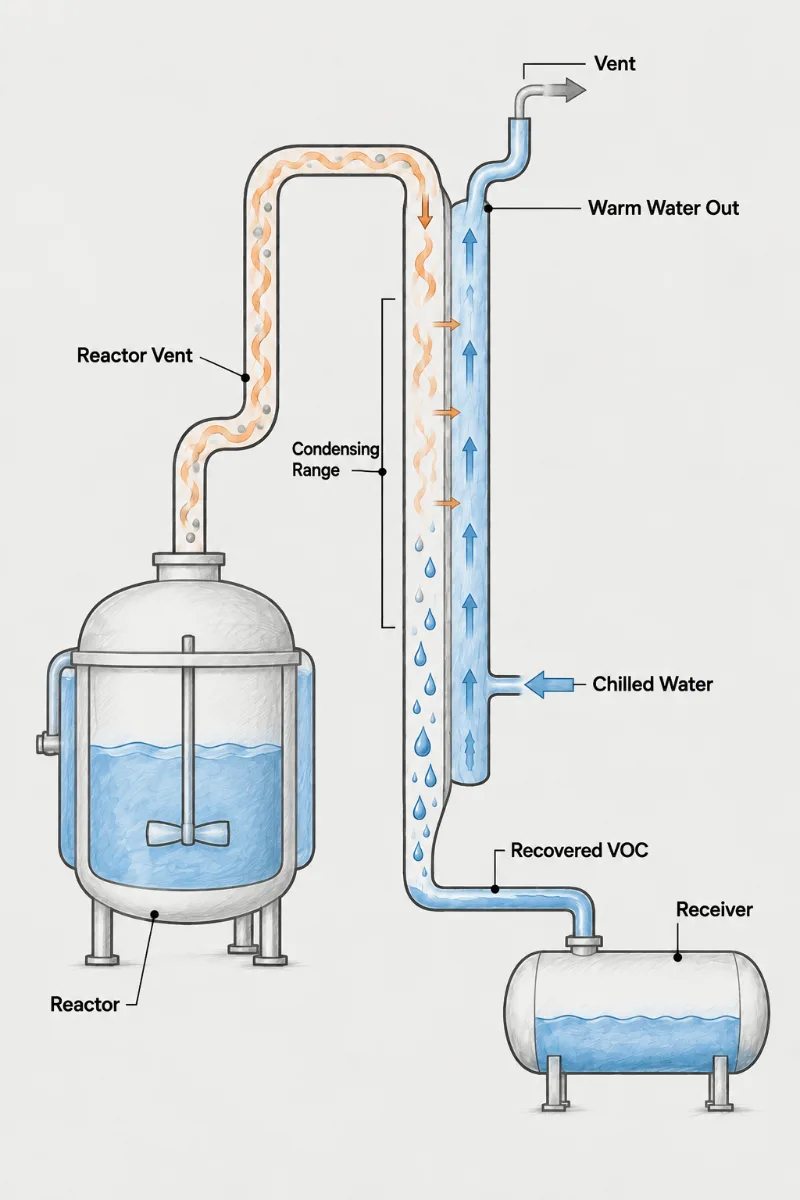
A reactor releases most of its VOC not during reaction but around it. Charging liquid displaces headspace gas already saturated with solvent. Pressure-purge and vacuum-purge inerting cycles sweep that headspace out with nitrogen. Heat-up expands the gas. Each event is short, rich in VOC and repeated every batch. A reactor vent condenser sits on that vent line, separate from the reflux condenser, and is sized for the spikes these steps create rather than for a steady flow.
- Displacement Rate: Gas leaves at the volumetric rate liquid enters, so the charge pump or gravity-fill rate sets the peak vent flow.
- Purge Cycles: Each nitrogen pressure-purge pushes out saturated headspace gas, and the number of cycles multiplies the VOC released per batch.
- Headspace Temperature: Warm reactor contents raise headspace saturation, so charging into a heated vessel releases far more VOC than a cold charge.
- Event Emissions: Permits often count pounds per batch, so the condenser is rated on mass removed per event as well as on peak flow.
- Shared Vents: Several reactors on one vent line can discharge together; size for the realistic overlap rather than every vessel at once.
- Solids Charging: Powder additions through a manway entrain dust and air into the vent, and a knockout ahead of the condenser protects it.
Spikes, Not Steady Flow: Rating a Reactor Vent Condenser
Reactor vent condensers are often sized from a steady flow that never actually occurs. The real flow is near zero for most of the batch and then several times the average for the minutes of a charge or a purge. A condenser rated on the average passes most of the VOC during exactly those minutes, and the batch emission record shows it.
Each event is a mass calculation first. Charging displaces a gas volume equal to the liquid added, at the saturation concentration for headspace temperature. A pressure-purge cycle releases about one headspace volume of gas for every atmosphere of purge pressure. A vacuum purge exhausts the headspace through the vacuum system, so that part of the load may belong on the pump instead. Summed, these give pounds per batch, and the condenser outlet temperature decides what share is released.
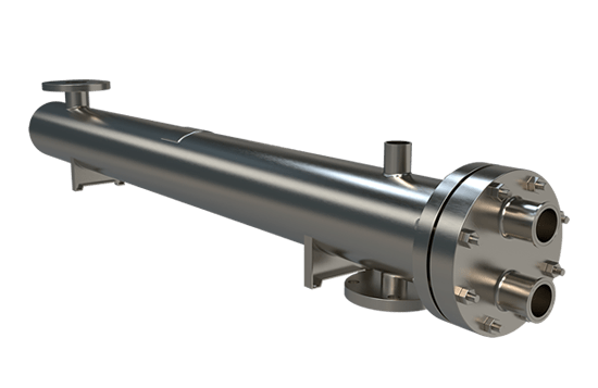
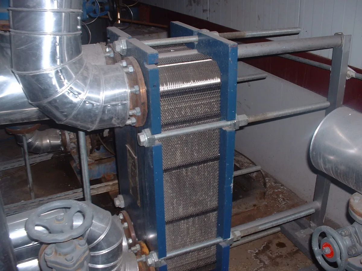
A Fixed Tubesheet shell-and-tube with gas in the tubes handles the spikes and cools quickly thanks to its modest holdup; it can be built in Hastelloy where reactor chemistry demands it and steamed out between campaigns. A Welded Plate exchanger offers a compact, close-approach unit for a crowded reactor bay and responds fast to sudden flow, though its gas side must be checked for pressure drop at the peak charging rate.
Bring the charging rates and volumes, purge method and cycles, headspace temperature during each step, solvents present, the number of reactors on the vent and the emission limit per batch or per hour.
Charging events
Liquid charge rate and volume for each addition
Inerting method
Pressure or vacuum purge, cycle count and purge pressure
Headspace conditions
Reactor temperature during charging, purging and heat-up
Batch emission limit
Allowed release per batch and reactors sharing the vent
Batch Emissions
Cut Where They Start
1.
Rated for the Spike
Area and gas velocity are chosen for the charging and purging rate, so the condenser holds its outlet temperature during the few minutes that release most of a batch's VOC.
2.
Fast Thermal Response
Low holdup and a surface already cold before the event mean the condenser is at full performance when the first displaced gas arrives, not halfway through the charge.
3.
Purge Gas Stays Lean
Nitrogen leaving each purge cycle is chilled before release, so inerting stops doubling as a solvent emission source and less solvent is lost from the batch.
Reactor vent questions
The reflux condenser sees pure boiling solvent vapor during reaction and returns it; the vent condenser sees nitrogen carrying solvent during charging, purging and heat-up, and it is a gas cooler as much as a condenser. The duties are opposite in character. A 1,000 gallon reactor charging methanol at 50 gpm pushes about 7 cfm of headspace gas out the vent, a trickle next to reflux vapor flow, but that gas is saturated and must be cooled from headspace temperature to a 35 F outlet to hold it.
The reflux unit, running on tower water, would pass most of that solvent straight through. Keeping the two separate also stops purge nitrogen from blowing through the reflux condenser and pushing vapor out of the still head.
Yes, and by more than most people expect, because headspace saturation follows the vapor-pressure curve rather than a straight line. Toluene saturates at about 7 percent by volume at 100 F but only 2 percent at 60 F, so charging into a cooled vessel cuts the solvent displaced per cubic foot of gas by about two thirds. The condenser then starts from a lower inlet concentration and reaches the same outlet with less surface or a warmer coolant.
The step that undoes the benefit is a reactor still warm from the previous batch: operators charge into 140 F headspace, where toluene saturation runs near 20 percent, and the vent record spikes. Cooling the jacket before the charge is cheaper than buying the condenser capacity to cover it.
When the reactor is inerted by pulling vacuum and breaking it with nitrogen, the solvent-laden headspace leaves through the vacuum pump, so a condenser on the vent header never sees it. Put condensing capacity where that gas goes. A suction-side condenser must work at the purge vacuum, where partial pressures are low and every inch of pressure drop lengthens the evacuation; a condenser on the pump discharge works at atmospheric pressure with far better odds.
If the same plant also pressure-purges, you may need both, or a header that routes the pump discharge back through the vent condenser. Check the pump too: a liquid-ring unit absorbing solvent in its seal water loses capacity and strips it out later as a second emission.
Yes, if the rating is built on a realistic overlap of charging and purge events and the shared line respects the lowest relief or vent setting among the vessels. If any two of four reactors could charge at once, size for two; if the batch scheduler never allows it, size for one with a modest margin. Add a check valve at each reactor so a pressure-purge on one vessel cannot push gas toward another that is open for sampling. Condensate from a shared unit carries whatever each reactor was running, so it goes to recovery rather than back to any one batch.