
1-805-484-2992
Quotes - Engineering - SalesCondensers in Sterilize-in-Place Service
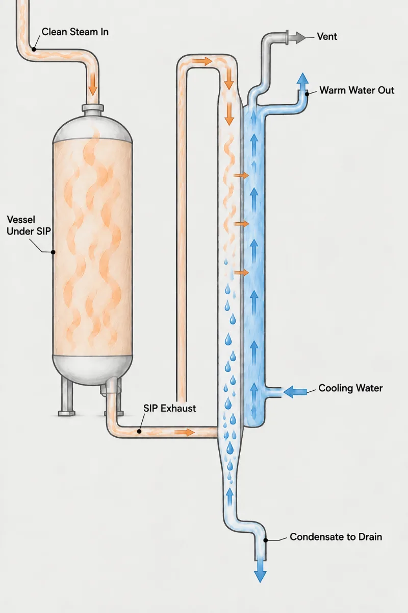
Sterilize-in-place pushes clean steam through tanks, transfer lines, filters and sometimes the condenser itself, holding every point at sterilizing temperature for a timed hold before cooling back to process conditions. Two condensing problems come with it. During the hold, condensate forms continuously on every cool surface and must leave through low-point drains or the temperature at that spot falls below setpoint. And a condenser inside the sterilization boundary goes from coolant service to full steam temperature and back on every cycle, a thermal swing most process condensers never see.
- Hold Temperature: Every wetted point must reach and stay at sterilizing temperature; pooled condensate in a shell or channel creates a cold spot that fails the thermocouple map.
- Air Removal: Air left in the high points of a bundle or head insulates the surface and stays cool; high-point vents must purge it during heat-up.
- Thermal Cycling: Each cycle moves tubes and shell between coolant and steam temperature, so the design must absorb differential expansion without loosening tube joints.
- Self-Drainage: The condenser itself must drain completely on both sides to its low point, since standing water both cools the hold and harbors contamination afterward.
- Coolant Sequencing: Cooling water is drained or isolated before steam-in and restored gradually afterward; a sudden cold slug onto hot tubes is the worst moment for the joints.
- Hold Condensate: Surface area and drains must carry off the steady condensate formed during the hold, which is highest at the start when metal is coldest.
When the Condenser Is Inside the Sterile Boundary
The SIP cycle fails at a condenser for one of two reasons: a thermocouple at the low point never reaches temperature, or a bundle that passed the first hundred cycles starts leaking at the tube joints. Both trace back to design choices. The first is drainage and venting. Condensate formed during heat-up has to run to a trapped low-point drain, and air displaced by the steam has to escape at the top; a horizontal shell with no slope or a channel with a pocket below the outlet nozzle will hold water and fail the hold.
The second is fatigue. During normal operation the tubes sit near coolant temperature; during SIP the whole unit climbs to sterilizing temperature, then cooling water returns. In a Fixed Tubesheet condenser the tubes and shell try to grow by different amounts each time, and the tube-to-tubesheet joints carry that load. Specify the SIP temperature, the number of cycles expected and the cool-down method so the design can include a shell expansion bellows or a controlled coolant restart rather than relying on the joint.
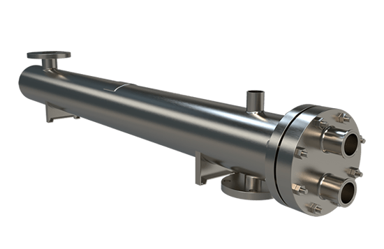
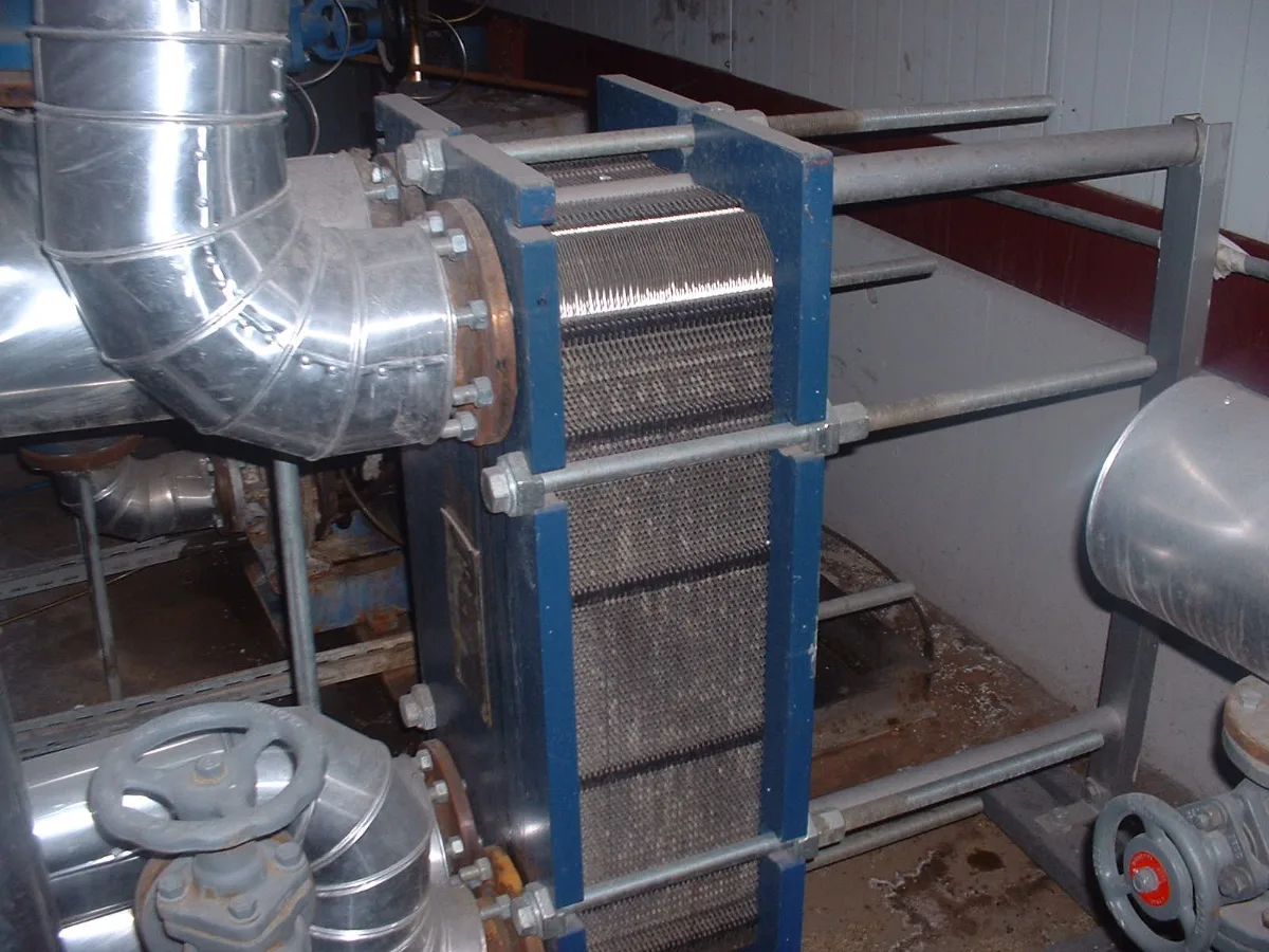
Mount the Fixed Tubesheet unit vertical or sloped so the tube side drains to one point, with the double tubesheet interspace vented. Mounted that way it is the construction most owners validate for SIP. A Gasketed Plate & Frame exchanger is a poor candidate inside the sterile boundary: gaskets age quickly under repeated steam exposure, and the corrugated channels resist complete drainage. Use plates on the coolant side of the system.
For a quote, send the SIP temperature and hold time, cycles per week, how cooling water is handled during the cycle, the orientation available, and where the steam traps and vents sit relative to the condenser.
Cycle profile
Sterilizing temperature, hold time and cycles per week
Coolant handling
Whether water drains, isolates or keeps flowing during sterilization
Mounting space
Vertical or sloped orientation and the available headroom
Drain and vent
Locations of traps, vents and temperature sensors around the unit
Designed for
Repeated Steam-In Cycles
1.
Passes the Cold Spot
Sloped or vertical mounting with a single low-point drain and a high-point vent lets condensate and air leave during heat-up, so the coldest thermocouple reaches setpoint within the hold.
2.
Joints That Last
Accounting for steam-in and coolant-restart temperatures in the mechanical design, with a shell bellows where needed, keeps tube joints tight over thousands of SIP cycles.
3.
Nothing Stands After
Complete drainage of tube and shell sides once the cycle ends removes residual condensate, so the sterilized condenser does not sit wet waiting for the next batch.
Sterilize-in-place questions
Because liquid or air is sitting at that point, and both hold the metal below steam temperature until they are displaced. Diagnose by timing. A sensor that climbs with the others and stalls 5 to 10 F short is usually sitting in pooled condensate; the drain is too small, its trap is losing prime or the nozzle sits above the true low point. A sensor that lags from the start and then jumps to setpoint is trapped air finally being pushed out, which means the high-point vent is undersized or closes too early.
Raising steam pressure hides both faults rather than fixing them. Slope the shell, move the drain to the lowest point and add a thermostatic air vent at the top of the head.
No, isolate and drain the shell before steam-in, because flowing coolant holds the tube wall tens of degrees below sterilizing temperature and turns the condenser in to a steam consumer during the hold. The coolant-side thermocouple never reaches setpoint while water runs. The next danger is the restart. Cold water slammed into a shell at 250 F shocks the tubes, and the differential strain goes straight into the tube-to-tubesheet joints; after a few hundred cycles they weep.
Restore flow through a small bypass first, letting the shell temperature fall over several minutes before opening the main valve. Write the sequence into the SIP recipe so the cool-down is automatic and the same every batch.
Thousands, when the cycle count and temperature swing are stated in the specification, so the mechanical design absorbs the differential expansion with a shell bellows or a controlled cool-down instead of asking the tube joints to carry it. The numbers behind that: 316L tubes rising from 60 F to 250 F grow about 0.02 inches per foot, so a 6 foot bundle tries to grow an eighth of an inch more than a shell that is still cool. Without a bellows, the joints take that load every cycle.
A plant running one cycle a day sees 365 cycles a year, so a ten-year life means rating the joints for 4,000 cycles with margin. State cycles per week and the cool-down method; they change the design more than the duty does.