
1-805-484-2992
Quotes - Engineering - SalesContinuous Column Condensing Service
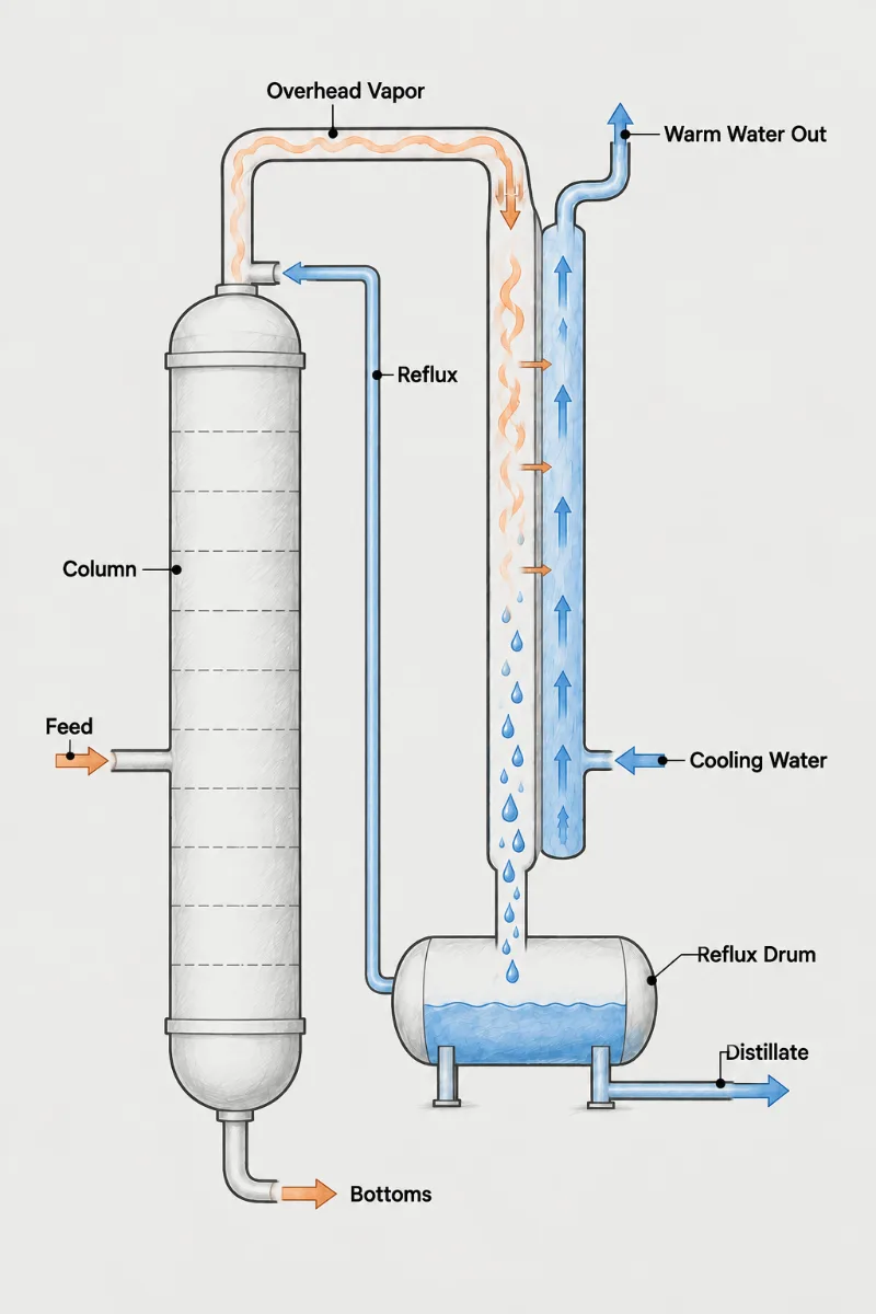
A continuous column runs at steady feed, steady boil-up and a fixed overhead composition for months between turnarounds. That stability is the main difference from batch work: the condenser has one well-defined design point, and its performance over a long run is governed by cooling-water fouling, column pressure control and how much margin was built in at the start. On a continuous column the condenser also sets column pressure, so its rating directly affects separation, reboiler duty and product specification across the whole unit.
- Design Point: Rate at normal overhead rate and composition, then confirm capacity at the maximum feed case the column was hydraulically designed to handle.
- Pressure Control: Column pressure is usually held by throttling coolant, flooding part of the surface, or hot-vapor bypass; each method changes how much area the condenser needs.
- Water Fouling: Tower water deposits scale over months of steady service, so a realistic TEMA fouling allowance and tube velocity above about three feet per second matter.
- Run Length: The condenser should last the full interval between turnarounds without cleaning; put the dirtier fluid where it can be rodded or hydroblasted during the outage.
- Heat Integration: Overhead vapor that condenses hot can preheat feed or make low-pressure steam before trim cooling, recovering energy that would otherwise go to the tower.
- Turndown Range: Reduced-feed operation lowers vapor velocity; confirm noncondensables still sweep to the vent and condensate still drains at minimum rates.
Steady-State Duty, Long-Run Margin
How much margin should a continuous-column condenser carry? Too little and tower pressure climbs every summer as cooling water warms and tubes scale; too much and the pressure controller spends its life nearly closed, which makes control sluggish. A practical approach is to rate the clean unit at design feed with the hottest expected coolant supply, then apply a fouling factor that reflects the actual water quality rather than piling on percentage oversizing.
The pressure-control method belongs in the specification. With a flooded condenser, part of the shell is deliberately filled with condensate and the liquid level varies the active condensing area, so extra surface is needed for the flooded portion and the outlet will be subcooled. With hot-vapor bypass, the condenser usually sits below the reflux drum and must stay fully drained. Coolant throttling is simplest but can drop tube velocity low enough to accelerate fouling.
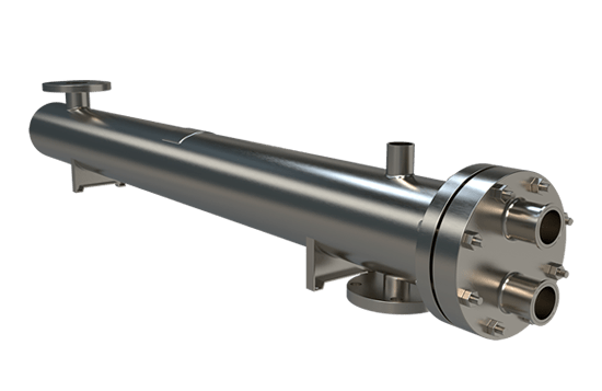
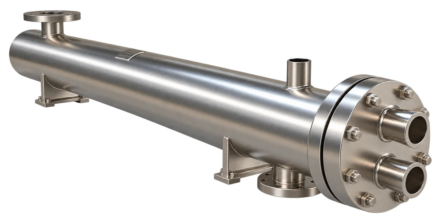
For most continuous overheads on cooling water, a Fixed Tubesheet exchanger with process vapor on the shell side and water through straight tubes is the default: the water side, which fouls, can be cleaned at turnaround, and there are no internal gasketed joints to leak. A U-Tube design earns its place when the overhead is hot enough relative to the coolant that differential expansion would otherwise call for a shell expansion joint, or when the bundle must come out for shell-side inspection.
Bring the column heat and material balance at design and maximum cases, the pressure-control scheme, cooling-water supply and return limits, water-quality data or the fouling factor your site uses, and the expected run length between turnarounds.
Heat balance
Design and maximum feed cases from the column simulation
Control scheme
Flooded, bypass or coolant-throttled pressure control
Water quality
Tower water chemistry, return limit and site fouling allowance
Turnaround interval
Months of service expected between planned cleanings
Engineered for
Months of Steady Service
1.
Sized for Fouled Duty
Rating includes a fouling allowance matched to your water, so column pressure holds at the end of the run, not just on startup day after the bundle was cleaned.
2.
Fits the Control Scheme
Surface, drainage and elevation are set for the pressure-control method you use, whether that means extra flooded area, a fully drained shell below the drum, or adequate tube velocity at reduced coolant flow.
3.
Recovers Overhead Heat
Where the overhead condenses hot enough, a first-stage exchanger can preheat feed or boiler water while a smaller trim condenser finishes the job, cutting cooling-tower load.
Long-run design questions
Column pressure climbs, the tops get hotter, and the operators spend reflux and reboiler steam to buy back the separation the fouled surface gave away. The arithmetic is unkind. A unit with a clean overall coefficient of 150 BTU/hr-ft2-F loses about a quarter of its capacity once 0.002 hr-ft2-F/BTU of scale builds on the water side, which is an ordinary summer on untreated tower water. The pressure controller first opens the coolant valve fully, then pressure creeps a few psi, and on a close-boiling separation that can move the top product off specification long before anyone considers cleaning. Trend the approach between condensing temperature and water outlet from the first week of a run; a steady rise is scale, a sudden one is usually gas.
Yes, flooded-condenser control is stable and cheap to instrument, as long as the extra surface for the flooded zone was in the rating and the drum sits where liquid can rise into the shell. Condensate under the level only subcools, at a coefficient perhaps a fifth of the condensing value, so a unit meant to run 20 percent flooded needs more then 20 percent extra surface to keep the same condensing capacity in reserve. It does not vent itself; inerts gather above the liquid and the controller reads them as more flooding, so a small bleed on a timer or a pressure differential alarm belongs in the design. Expect subcooled reflux, and tell the column designer, because the top tray will see more liquid than the flow meter reports.
Cooling water belongs in the tubes on a continuous overhead, and the pass count should be set so the velocity holds near 5 ft/s at design flow, not just above the minimum. A worked case: 300 gpm through 3/4 inch, 16 BWG tubes at 5 ft/s needs roughly 64 tubes per pass, so a 256-tube bundle would be built four-pass rather than two. That velocity scrubs the tube wall for months, keeps the fouling factor honest, and still leaves the shell side free for the vapor, which can tolerate almost no pressure drop. Put the overhead in the tubes only when its design pressure would otherwise force a heavy shell, or when the overhead itself fouls and must be rodded at turnaround.
Set the margin with a measured fouling factor and the hottest coolant day, and resist a flat percentage on top of that. Fouling factors from 0.001 to 0.002 hr-ft2-F/BTU on treated tower water already add 15 to 30 percent of surface at typical coefficients; stacking another 25 percent on top gives a condenser that, on a 60 F winter morning, has roughly twice the driving force of a summer afternoon with the same duty. The control valve then sits almost closed, tube velocity falls, and the water side scales faster than the fouling factor assumed, so the oversizing creates the fouling it was meant to cover. If a future capacity increase is the real reason for margin, state the future case and rate it as a second design point instead.
Yes, and a continuous column is the best candidate on the site for it, because the load changes little from one month to the next. An overhead condensing at 250 F can preheat column feed or raise steam at a few psig in a first exchanger, with a smaller trim condenser on cooling water finishing the job. Keep two things in the specification. The trim unit should hold column pressure on its own at a reduced rate during startup, when there is no feed to heat, and the recovery exchanger should see the dirty fluid on the side that can be cleaned, since it now sits inside the process loop rather than at the end of it. Payback on the extra shell is often inside a year when the alternative is fired reboil.