
1-805-484-2992
Quotes - Engineering - SalesOverhead Condensers for Distillation Columns
The overhead condenser takes the vapor leaving the top tray or packing of a distillation column and turns it into liquid for reflux and distillate. It is the heat sink for the entire tower: everything the reboiler puts in, less what leaves with the products, comes out here. Where the condenser sits, how far from the column outlet, how high above the reflux drum, and how it is supported, shapes its design as much as the thermal rating does, which is why overhead condensers are specified alongside the column layout rather than after it.
- Elevation: The condenser must sit high enough that condensate drains by gravity into the reflux drum with liquid head to spare, without trapping liquid in the shell.
- Vapor Line: Large vapor piping from the column top adds pressure drop and cost; placing the condenser close to the column outlet keeps the line short and tower pressure stable.
- Inerts Venting: Air, nitrogen or light gas from the feed collects at the cold end; the vent nozzle belongs where those gases concentrate, normally above the condensate outlet.
- Orientation: Horizontal units with vapor on the shell side keep pressure drop low; vertical units save plot space and drain fully but need tube-side vapor velocity checks.
- Support Loads: A water-filled condenser on a structure or stacked on the drum is heavy; filled weight and nozzle loads should reach the structural engineer early.
- Drum Connection: The condensate line to the drum needs a seal or a vapor balance line so drum vapor does not push back up and hold liquid in the condenser.
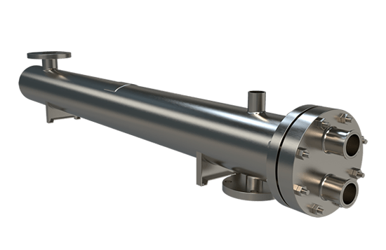
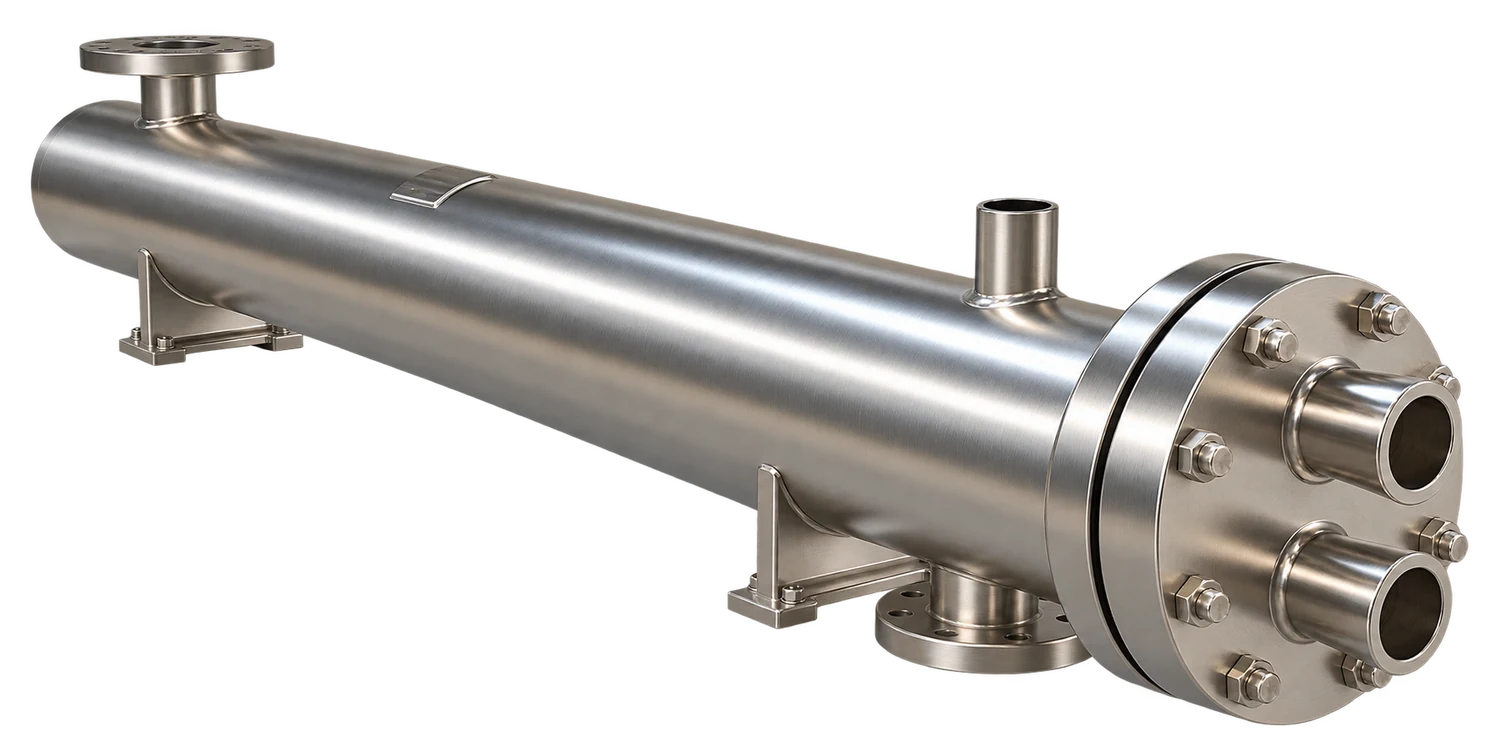
Where the Overhead Condenser Sits Changes How It Is Built
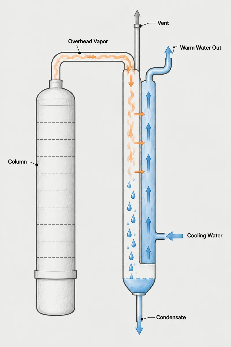
A recurring overhead problem has nothing to do with surface area: the condenser is large enough on paper, yet column pressure swings and capacity falls short. The usual cause is drainage. If the condensate outlet sits too close in elevation to the reflux drum, or the drum has no vapor balance line back to the condenser, liquid backs up into the shell, covers tubes, and the active condensing surface shrinks. The tower experiences that as lost cooling.
Mechanical arrangement therefore gets settled with the layout. Horizontal overhead condensers on a structure beside the column, with vapor entering the top of the shell and condensate leaving the bottom into a drum below, are the most common arrangement and the easiest to maintain. Vertical units at grade or stacked above the drum use less plot area. Some plants mount the condenser directly on the column head and do without a vapor line altogether, returning liquid by gravity.
A Fixed Tubesheet design with water in the tubes is the standard overhead build for moderate temperature differences, since tubes can be cleaned without disturbing column piping. Where the overhead runs hot and the cooling water cold, a U-Tube bundle removes the need for an expansion joint and can be withdrawn for inspection, provided the structure leaves pull space at the channel end. Plan that clearance before steel is set. To quote an overhead condenser accurately, send the overhead vapor rate and composition, top pressure and drum pressure, cooling-medium data, and a sketch or plot plan showing column, condenser and drum elevations.
Column top
Overhead rate, composition and top tray pressure
Layout sketch
Column, condenser and drum elevations with pull space
Drum details
Drum pressure, liquid level and vapor balance line
Cooling medium
Supply temperature, return limit and available flow
Laid Out
With the Column and Drum
1.
Gravity Drainage
Condensate outlet height, nozzle size and balance-line connection are set so liquid leaves freely into the reflux drum and never accumulates over the tube bundle.
2.
Short Vapor Run
Locating and orienting the condenser for the shortest practical overhead line keeps pressure loss off the column top, where every psi added also raises bottoms temperature.
3.
Maintenance Access
Bundle pull direction, channel cover clearance and water-side cleaning access are planned with the structure, so turnaround crews can pull the bundle or rod the tubes without cutting piping or removing platform steel.
Layout and elevation questions
Its height is set by the drum beneath it, not by the column. The condensate outlet needs enough height over the drum's maximum liquid level to drive condensate through the line at full rate, and that is usually a few feet. A condensate line sized for 3 ft/s on a 20,000 lb/hr overhead might lose a foot of head in fittings and the inlet nozzle, so 3 to 5 ft of static head above the high level is a common target. Higher is wasted structure, lower risks liquid backing into the shell. On a vacuum tower the vapor line is the heavier cost; a 24 inch line is cheaper to keep short than to run 30 ft, which is why the condenser often ends up on a platform tight against the column.
Something is covering tubes, and the two candidates are condensate that cannot leave and inert gas that cannot be vented. Read the condensate temperature first. Liquid leaving 20 F or more below the overhead bubble point means a flooded shell, because only submerged tubes subcool that far; check the drum level, the balance line and whether the outlet nozzle was piped with a pocket. Liquid leaving near the bubble point while pressure still climbs points to gas: a vent at the wrong end, a closed vent valve, or a nitrogen purge upstream that nobody counted. Each one looks like lost area from the control room, and neither responds to a bigger exchanger. Trend the condensate temperature and the vent flow together and the cause usually shows itself within a shift.
Yes, and on columns up to a few feet in diameter it is often the neatest arrangement, with the condenser bolted to saddles on the drum and condensate dropping straight down. Count the weight before committing. A 30 inch by 16 ft shell holds roughly 2,500 lb of water in its tubes and shell alone, and the operating weight with condensate and piping can pass 15,000 lb, all of which the drum saddles and foundation must carry through wind and seismic cases. Leave bundle pull length at the channel end, which is where stacked units are most often boxed in. For larger columns a separate structure beside the column usually costs less than the reinforced drum the stack would need.