
1-805-484-2992
Quotes - Engineering - SalesColumn-Mounted Reflux Condensers
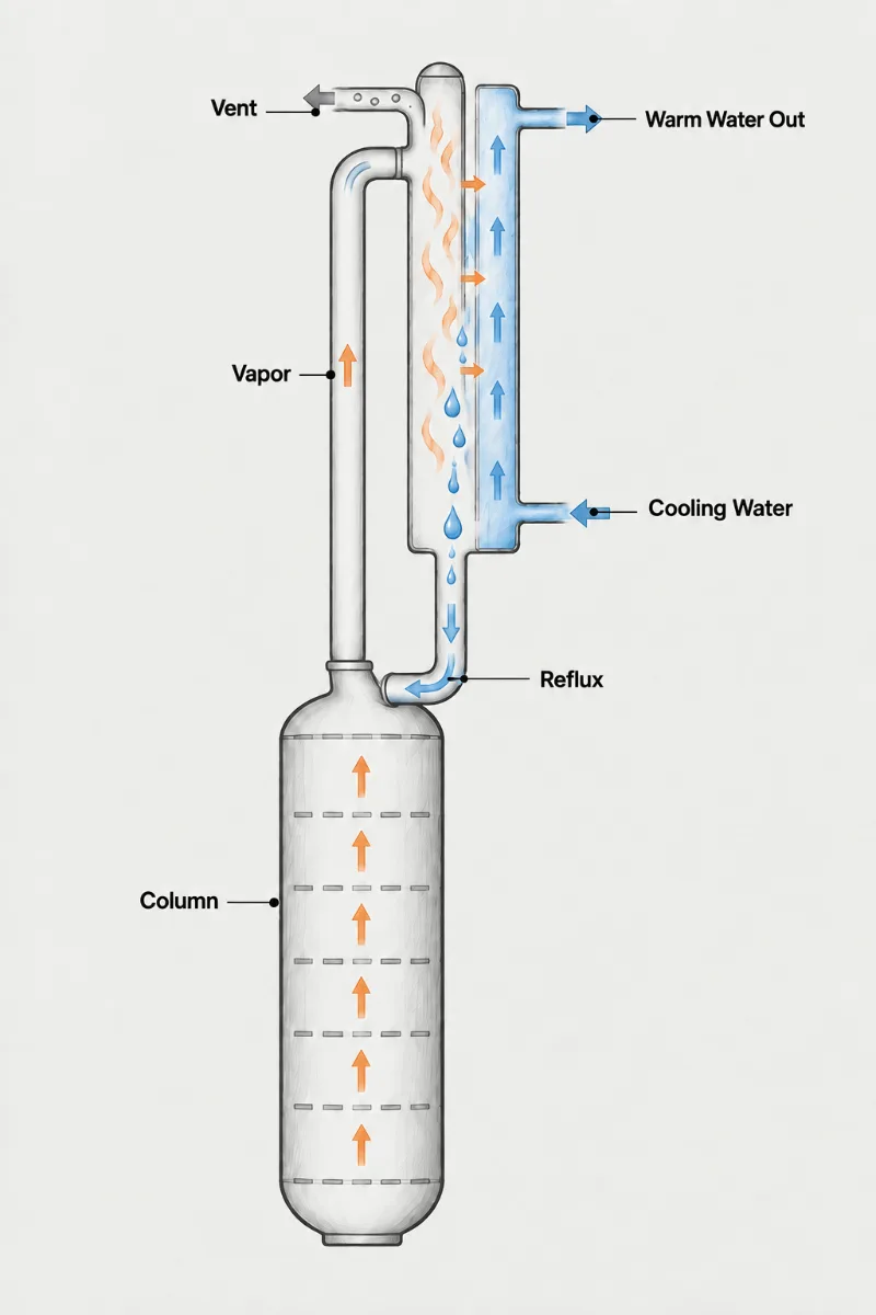
A reflux condenser in the strict sense sits directly on the column or vessel head and returns its condensate straight down by gravity, with no reflux drum, pump or control valve in between. Vapor rises into the tubes, condenses on the cold walls, and the liquid runs back down against the rising vapor. The arrangement is compact and simple and is common on small columns, pilot units and reactors, but it places a hard limit on vapor velocity: push the vapor too fast and liquid is carried up instead of draining back.
- Flooding Limit: Upflowing vapor must stay below the velocity at which it holds liquid up in the tubes; tube count and diameter are set by this limit first.
- Tube Diameter: Larger tubes, typically one inch and up, tolerate higher vapor rates before flooding than small-bore tubes and drain more freely back to the column.
- Vertical Mounting: The condenser must stand plumb on the column head; even a slight tilt sends condensate down one side of the bundle and starves the rest.
- No Reflux Drum: Without a drum there is no reflux ratio set by a valve; reflux is everything condensed, so coolant rate becomes the only lever.
- Vent Condenser: Uncondensed vapor and inerts leave the top; a small trim condenser on colder coolant often follows to catch what slips past.
- Head Loads: The full weight of a water-filled condenser rests on the column nozzle and head, which must be checked for that load plus wind and seismic forces.
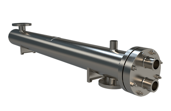
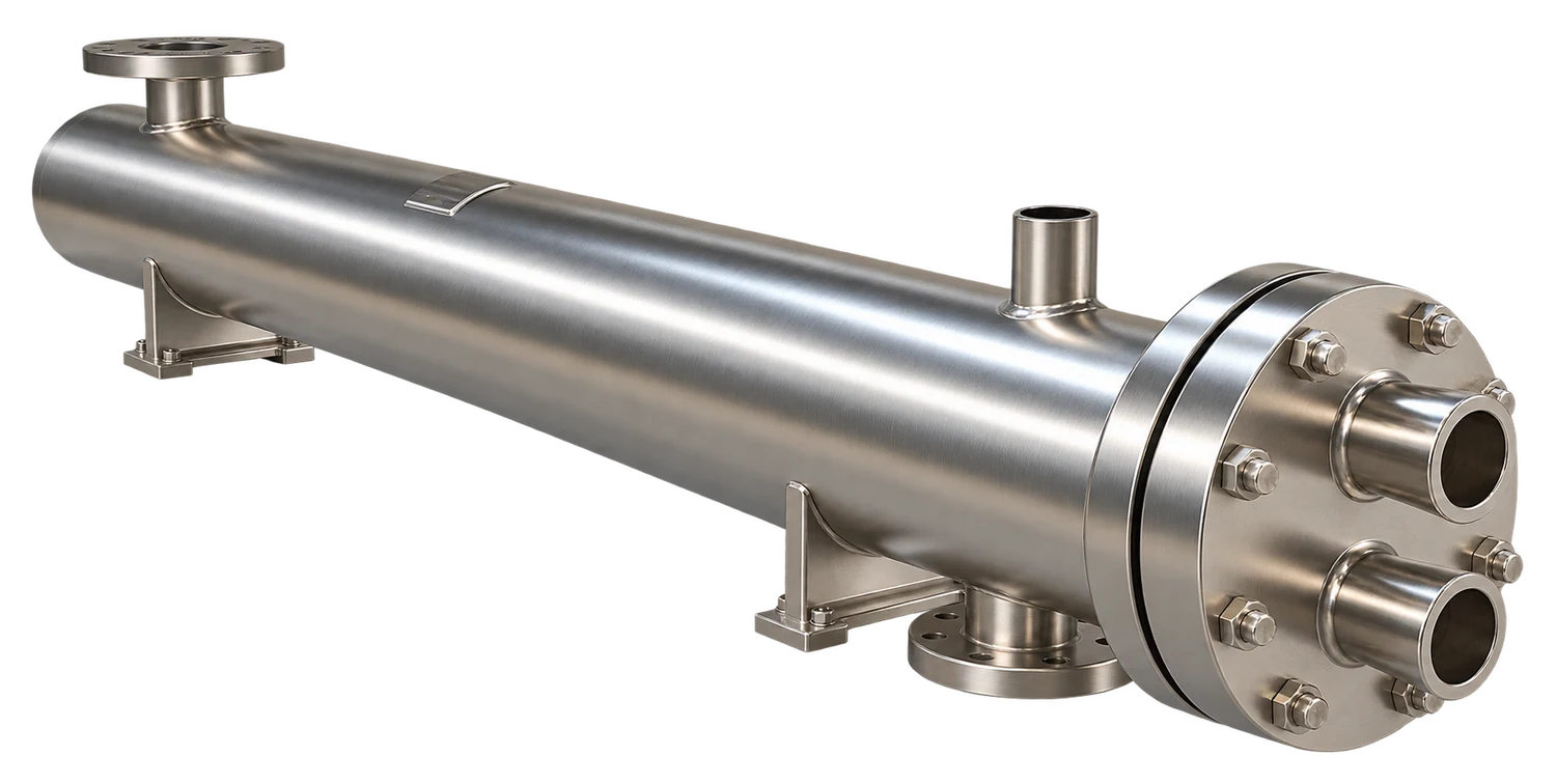
Countercurrent Condensing Right on the Column
When vapor and its condensate travel in opposite directions inside the same tube, the governing question is not heat transfer area but whether the liquid can get back down. Each tube carries a falling liquid film being sheared by rising vapor. Above a certain vapor velocity, set by tube diameter, liquid and vapor densities and surface tension, the film stalls, liquid accumulates, and the unit floods. Flooding shows up as surging column pressure and liquid slugging out the top vent. Rate a column-mounted reflux condenser against a flooding correlation first, then add the area needed for heat transfer; a design that starts from area and ignores flooding is the classic failure.
A Fixed Tubesheet exchanger mounted vertically, with vapor in straight tubes and coolant on the shell side, is the normal construction, because straight vertical tubes drain cleanly and present a uniform inlet to the rising vapor. Inlet tube ends are often cut at an angle or tapered to help liquid leave against the vapor. A U-Tube bundle does not suit this service: the bend cannot drain countercurrent liquid, and the return leg would carry condensate the wrong way. Where a U-Tube is used near a column, it is as a downstream vent or trim condenser with vapor on the shell side.
Because all condensed liquid returns, reflux rate follows coolant rate, and over-cooling subcools the returning liquid, which condenses more vapor on the top tray and raises internal reflux. When requesting a quote, bring the vapor rate and composition, liquid and vapor densities if known, nozzle size on the column head, coolant data and the allowable height above the column.
Head nozzle
Size and rating of the column connection
Vapor upflow
Maximum vapor rate rising from the column top
Fluid properties
Liquid and vapor densities with surface tension
Height limits
Headroom above the column and structural capacity
Gravity Return
With No Drum or Pump
1.
Checked Against Flooding
Tube size and count are chosen so peak vapor rate stays safely below the flooding velocity, which keeps condensate draining back to the column instead of slugging out the vent.
2.
Fewer Components
Eliminating the reflux drum, pump and control valve removes seal leaks, pump maintenance and plot space, which makes sense on smaller columns, pilot units and reactor service.
3.
Built-In Rectification
Countercurrent contact between rising vapor and returning liquid inside the tubes adds a degree of separation, so vapor leaving the top is somewhat richer in the light component.
Column-mounted reflux questions
You cannot set the reflux ratio directly, so you set it by what you choose not to condense: coolant flow to the column-mounted unit fixes how much vapor returns, and the balance passes to a second condenser that makes distillate. The arithmetic is simple. If the column boils up 1,000 lb/hr and the reflux condenser is trimmed to condense 750 lb/hr, the reflux ratio is 3 to 1 and 250 lb/hr goes to the product condenser. The lever is coarse at low coolant flows, so a tempered loop with a control valve on the reflux unit works better than a hand valve on tower water. Watch the second condenser as well; if it is on colder coolant it can pull vapor through faster than intended and lower the ratio without anyone touching the first.
The reliable sign is liquid where only vapor should be: condensate slugging out the top vent or showing in the vent condenser, with column pressure surging rather than drifting. Pressure drop across the unit jumps as well, often several inches of water on a condenser that normally shows almost none, and the surges track heat input. Cut the reboiler or pot steam 10 percent and a flooded unit settles within minutes, while an undersized one only passes a little less vapor. Infrared on the shell is a cheap confirmation: a flooded bundle runs cold near the bottom tubesheet where liquid is held up and hot above it. Expect to see it first in summer, when warmer coolant means more vapor reaches the upper tubes.
Yes, with the condition that the gas the reaction makes is included in the flooding check and the vent is sized for it, since the condenser now sees gas plus vapor rising together. A reactor evolving 50 lb/hr of hydrogen chloride or carbon dioxide at the same time as 2,000 lb/hr of solvent vapor adds little heat load but a great deal of upward velocity at the bottom of the tubes, which is where flooding starts. Foam is the other difference; a reaction that foams can carry liquid into the tubes and the condenser then runs as a knock-back for froth rather than vapor. Fit the head nozzle with a short, straight run, keep the tube count generous, and give the vent gas its own small trim condenser on colder coolant.
Subcooling is a problem on a column-mounted unit because every degree of it goes straight to the top tray and condenses more vapor there, so the column runs at a higher internal reflux than the heat balance assumed. Quantify it: reflux returned 30 F below its bubble point, with a specific heat of 0.5 and a latent heat of 150 BTU/lb, condenses an extra 10 percent of vapor on the top tray. The reboiler pays for that, and on a pilot column it is often the reason the product rate is lower than the simulation predicted. A few degrees of subcooling is harmless. Hold it there with a tempered loop set to leave the coolant near 20 F below the condensing temperature, rather than running raw chilled water through a bundle sized for summer tower water.
Larger tubes raise the velocity at which rising vapor stops the falling film, so a bundle of 1 inch tubes carries more vapor before flooding than the same surface in 5/8 inch tubes. The flooding limit climbs roughly with the square root of tube diameter, which means going from 5/8 inch to 1 inch buys about 25 percent more allowable vapor velocity for the same vapor and liquid properties. The price is fewer tubes in a given shell and a lower surface density, so the unit gets taller or wider, which the head nozzle and the structure must carry. On atmospheric solvent service in 1 inch tubes the limit commonly falls below 10 ft/s; under vacuum, where the vapor is lighter, the allowable velocity rises but the mass rate it represents falls.